Method of performing a transforaminal posterior lumber interbody fusion procedure

Inactive Publication Date: 2007-06-05
SYNTHES USA
View PDF162 Cites 202 Cited by
  • Summary
  • Abstract
  • Description
  • Claims
  • Application Information

AI Technical Summary

Benefits of technology

[0010]In yet another aspect, a method for implanting an intervertebral implant into an affected disc space of a patient via a transforaminal window is described. The transforaminal window is created and bone graft material is inserted into the affected disc space. Using an insertion tool, an implant is inserted into the affected disc space via the transforaminal window, the implant having an arcuate body with curved, substantially parallel posterior and anterior faces separated by two narrow implant ends, superior and inferior faces having a plurality of undulating

Problems solved by technology

A number of medical conditions such as compression of spinal cord nerve roots, degenerative disc disease, herniated nucleus pulposis, spinal stenosis and spondylolisthesis can cause severe low back pain.
The T-PLIF approach avoids damage to nerve structures such as the dura and the nerve root, but the resulting transforaminal window available to remove the affected disc, prepare the vertebral endplates, and insert the implant is limited laterally.
However, as these devices were not designed specifically for the T-PLIF procedure, they are not shaped to be easily insertable into

Method used


Image

  • Method of performing a transforaminal posterior lumber interbody fusion procedure
  • Method of performing a transforaminal posterior lumber interbody fusion procedure
  • Method of performing a transforaminal posterior lumber interbody fusion procedure

Examples


Embodiment Construction

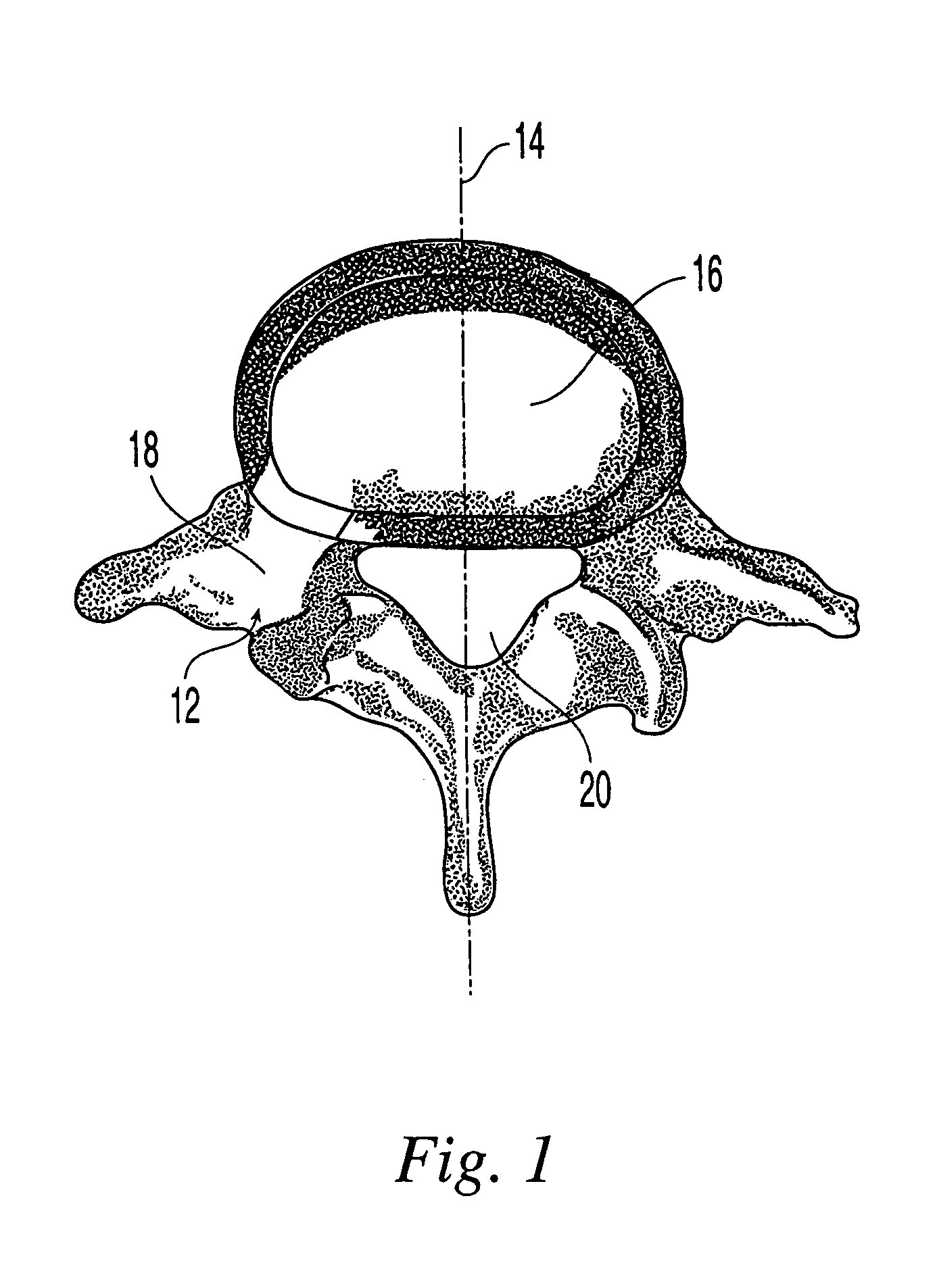
[0040]An implant according to the present invention, referred to herein as a transforaminal posterior lumbar interbody fusion implant (“T-PLIF implant”), is designed for use as an intervertebral spacer in spinal fusion surgery, where an affected disk is removed from between two adjacent vertebrae and replaced with an implant that provides segmental stability and allows for bone to grow between the two vertebrae to bridge the gap created by disk removal. Specifically, the T-PLIF implant is designed for the transforaminal lumbar interbody fusion (T-PLIF) technique, which, as shown in FIG. 1, involves a posterior approach 12, offset from the midline 14 of the spine, to the affected intervertebral disk space 16. The window 18 available for implant insertion using the T-PLIF technique is limited laterally by the dura 20 and the superior exiting nerve root (not shown).

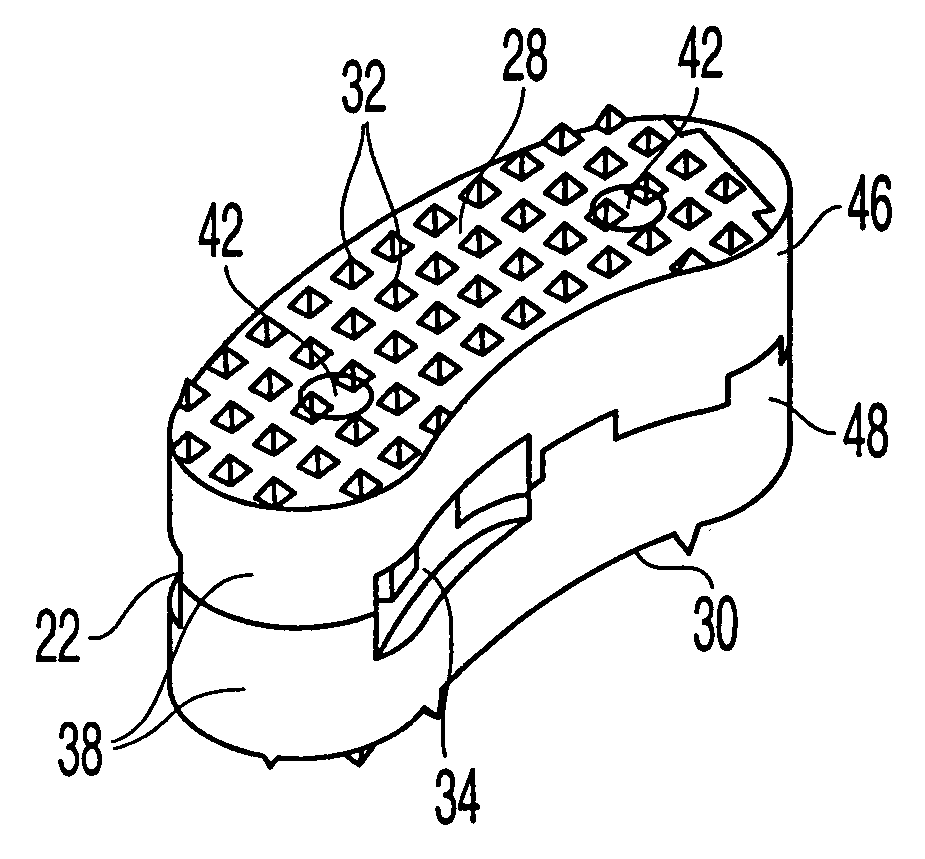
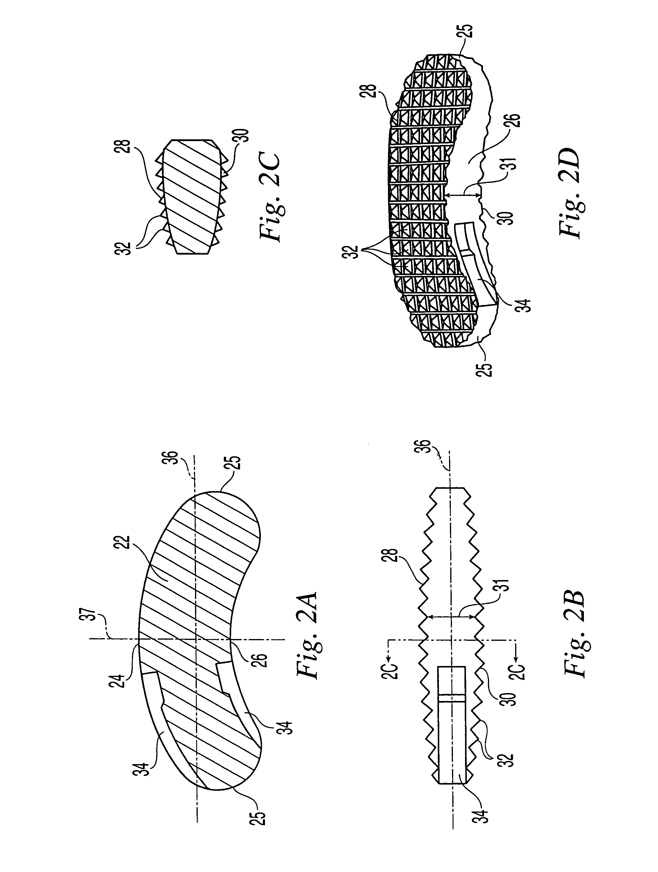
[0041]As shown in FIGS. 2A through 2D, in a preferred embodiment, the T-PLIF implant has an arcuate, “rocker-like” body 22...


PUM


Abstract

An intervertebral implant for fusing vertebrae is disclosed. The implant has a body with curved, substantially parallel posterior and anterior faces separated by two narrow implant ends, superior and inferior faces having a plurality of undulating surfaces for contacting upper and lower vertebral endplates, and at least one depression at a first end for engagement by an insertion tool. The arcuate implant configuration facilitates insertion of the implant from a transforaminal approach into a symmetric position about the midline of the spine so that a single implant provides balanced support to the spinal column. The implant may be formed of a plurality of interconnecting bodies assembled to form a single unit. An implantation kit and method are also disclosed.

Description

CROSS-REFERENCE TO RELATED APPLICATIONS[0001]The present application is a divisional of U.S. patent application Ser. No. 09 / 848,178, filed May 3, 2001, now U.S. Pat. No. 6,719,794, the contents of which is expressly incorporated herein by reference thereto.FIELD OF THE INVENTION[0002]The present invention is directed to an intervertebral implant, its accompanying instrumentation and their method of use. More particularly, the present invention is directed to an intervertebral implant and instrumentation for use in a transforaminal posterior lumbar interbody fusion procedure.BACKGROUND OF THE INVENTION[0003]A number of medical conditions such as compression of spinal cord nerve roots, degenerative disc disease, herniated nucleus pulposis, spinal stenosis and spondylolisthesis can cause severe low back pain. Intervertebral fusion is a surgical method of alleviating low back pain. In posterior lumbar interbody fusion (“PLIF”), two adjacent vertebral bodies are fused together by removin...

Claims


Application Information

Patent Timeline
IPC IPC(8): A61F2/44A61B19/00A61B17/56A61B17/16A61F2/00A61F2/28A61F2/30A61F2/46
CPCA61B17/1671A61F2/4465A61F2/4611A61F2/4684A61B17/1604A61F2310/00359A61F2/28A61F2002/2835A61F2002/3008A61F2002/30133A61F2002/30383A61F2002/30492A61F2002/30507A61F2002/30538A61F2002/30594A61F2002/30604A61F2002/30787A61F2002/30797A61F2002/30843A61F2002/30904A61F2002/30975A61F2002/4628A61F2220/0025A61F2230/0015A61F2250/0006A61F2250/0098A61F2310/00017A61B17/1659
Inventor GERBER, DAVIDMESSERLI, DOMINIQUEPAUL, DAVID
Owner SYNTHES USA
Why Eureka
Try Eureka