Polymer underwater pelletizer apparatus and process incorporating same

a technology of underwater melt and pelletizer, which is applied in the field of underwater melt pelletizer die improvement, can solve the problems of clogging the die hole (and presumably other parts of the die), hazard for operators, and other methods that have not proved very effective for higher melting and/or fast freezing of polymers

Inactive Publication Date: 2007-06-05
TICONA LLC
View PDF19 Cites 34 Cited by
  • Summary
  • Abstract
  • Description
  • Claims
  • Application Information

AI Technical Summary

Benefits of technology

[0011]It is therefore an object of the present invention to provide an apparatus suitable for polymer pelletization which minimizes the potential for the freezing of polymer. A feature of the present invention is the strategic incorporation of thermally conductive materials into such apparatus to facilitate polymer flow. An advantage of the present invention is the attendant savings in cost and time through more efficient and consistent operation of the UMP's equipped with such apparatus. These and other objects, features and advantages of the invention as disclosed and claimed herein will become apparent upon having reference to the following detailed description of the invention.
is the attendant savings in cost and time through more efficient and consistent operation of the UMP's equipped with such apparatus. These and other objects, features and advantages of the invention as disclosed and claimed herein will become apparent upon having reference to the following

Problems solved by technology

If the TP has a high melting point enough heat may be removed from the TP and also the face of the die plate which is in contact with water to also freeze some of the polymer which has not exited the die hole, thereby clogging that die hole (and presumably others in the die).
This can be rectified to some extent by using heated water (which itself may be a burn hazard for the operators).
However these and other methods have not proved very effective for higher melting and / or fast freezing polymers.

Method used


Image

  • Polymer underwater pelletizer apparatus and process incorporating same
  • Polymer underwater pelletizer apparatus and process incorporating same
  • Polymer underwater pelletizer apparatus and process incorporating same

Examples


examples

[0049]Procedure

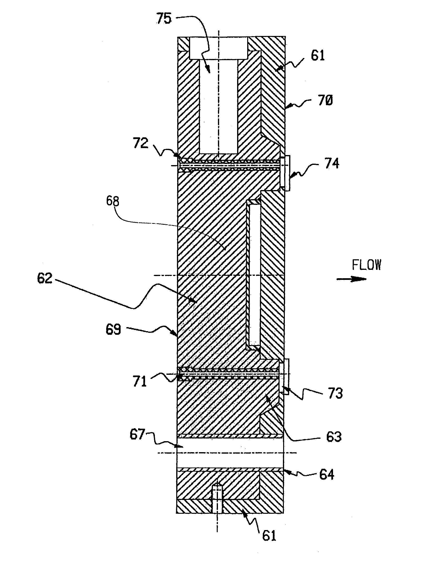
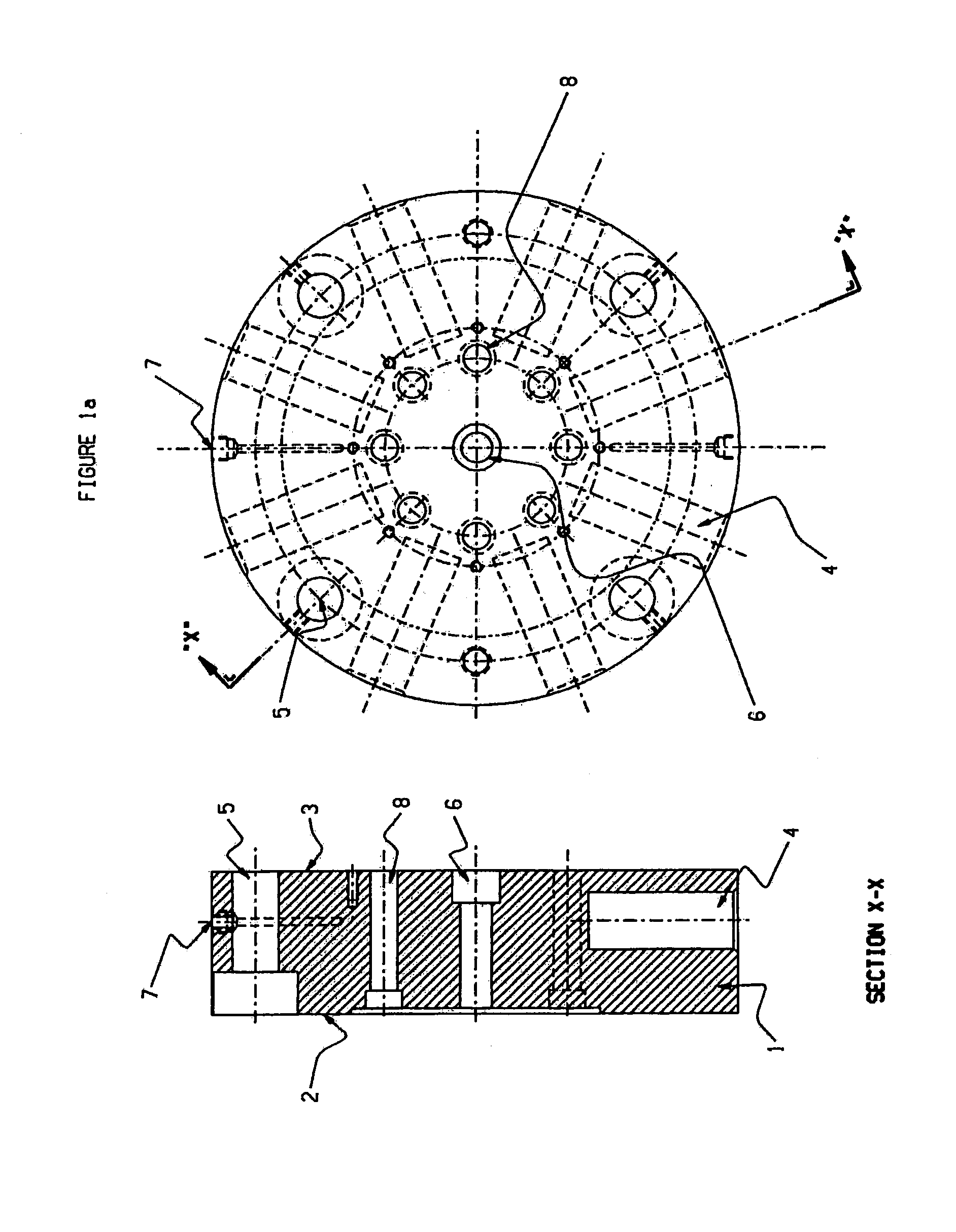
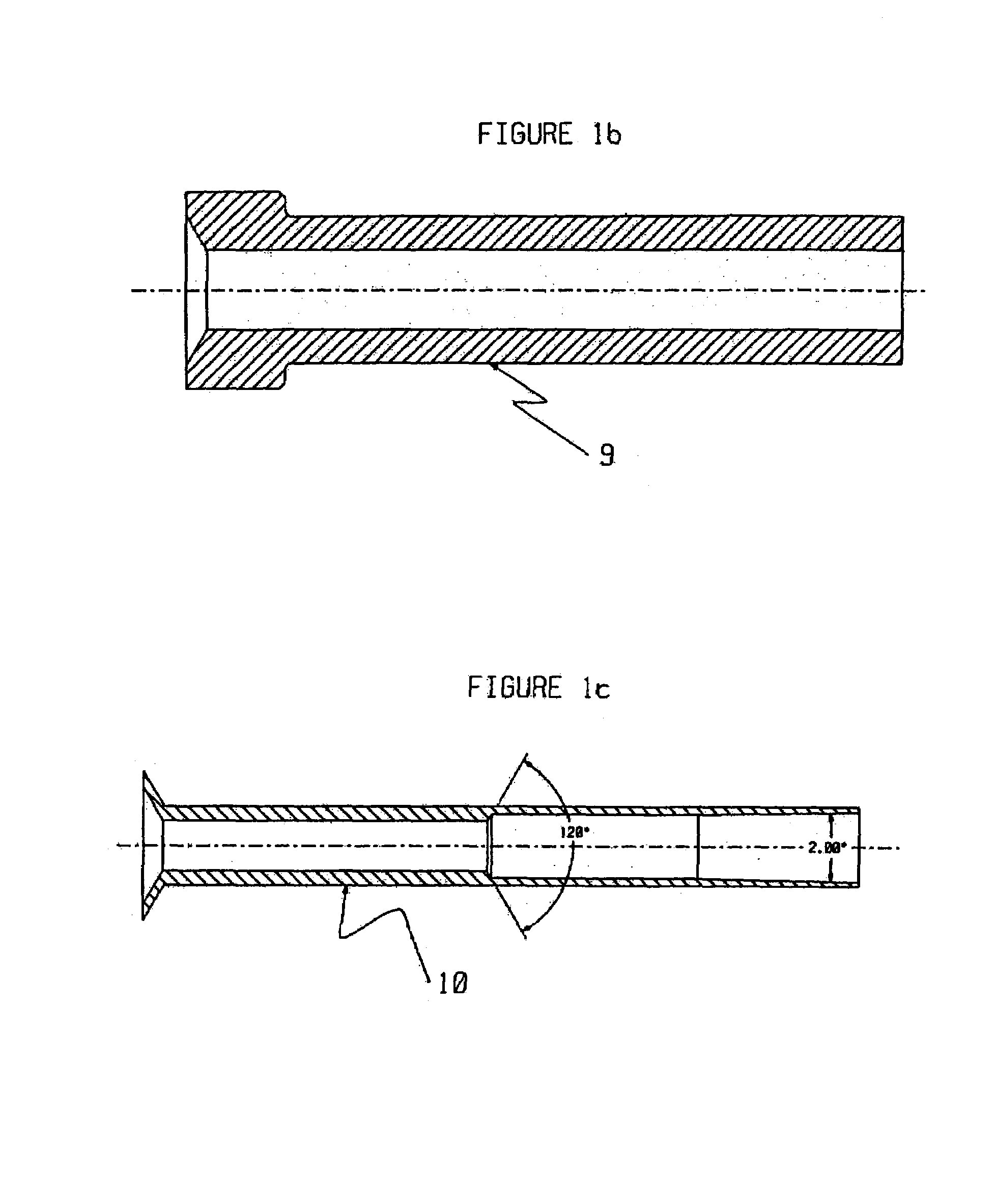
[0050]In the Examples dies with certain designs are used. They are described below:[0051]Die A This die was made from a soft brass, 360 Brass alloy. Although it operated well, after a short period of operation the die was deformed (bulged) from the operating pressures, and was taken out of service. This die was identical in all material respects to the die shown in FIG. 1, and has an overall diameter of 22.86 cm and 4.21 cm thick. The die was bolted to the extruder end. The eight die holes were fitted with insert holders such as 9, which in turn could be fitted with die inserts such as 10, or be plugged so that less than 8 dies holes were in operation. The insert holder and inserts were also made of 360 Brass. The die was also equipped with a layer of thermal insulation over the exit end of the die holes similar to 33 in FIG. 2 which was made from titanium carbide. In the inserts 10 the taper angle, 88, was 2°, a zone similar to 85 was 5.14 cm long (including the tran...


PUM

PropertyMeasurementUnit
tensile yield strengthaaaaaaaaaa

Abstract

Underwater melt pelletizer dies which have a highly thermally conductive pathway from their heating source to the vicinity of the polymer exit end of their die holes and have a thermally insulating material at that end of their die holes have improved operability and can pelletize thermoplastics which are otherwise difficult or impossible to pelletize with such an apparatus.

Description

CROSS REFERENCE TO RELATED APPLICATIONS[0001]This application claims the benefit of U.S. Provisional Application No. 60 / 490,990, filed Jul. 30, 2003.FIELD OF THE INVENTION[0002]The present invention relates to improved underwater melt pelletizer dies containing a highly thermally conductive pathway. More particularly, the present invention relates to such dies having such pathways extending from the die's heating source to the vicinity of the exits of the die holes, and is insulated from the cooling medium at the exits of the die holes, and together with processes using such dies.BACKGROUND OF THE INVENTION[0003]Thermoplastics (TPs) are very important items of commerce. Typically they are formed into various parts and shapes by melt forming, that is melting of the TP, forming it while molten into a shape and then cooling the TP to a solid to “fix” it in that shape. In most melt forming machines, the TP is fed in the form of a pellet or granule, typically in the size range of 0.1 to ...

Claims


Application Information

Patent Timeline
Patent Type & Authority Patents(United States)
IPC IPC(8): B29C47/12B01J2/20B29B9/06B29C31/00B29C48/04B29C48/05B29C48/30B29C48/345
CPCB01J2/20B29B9/065B29C47/0011B29C47/30B29C31/00B29C47/00B29K2995/0013B29C48/00B29C48/04B29C48/345B29C48/05B29B7/826B29B7/582B29B7/823B29B9/06B29B9/02
Inventor JACKSON, RICHARD ALANROYER, DENNIS JACKWAGGONER, MARION GLEN
Owner TICONA LLC
Why Eureka
Try Eureka