Light element with a translucent surface

a technology of light elements and translucent surfaces, applied in the direction of lighting and heating apparatus, renewable energy machines, instruments, etc., can solve the problems of large consumption of electric power in many high-rise buildings, severe temperature increases, and inhomogeneous light distribution

Inactive Publication Date: 2007-06-05
POWERPULSE HLDG
View PDF28 Cites 37 Cited by
  • Summary
  • Abstract
  • Description
  • Claims
  • Application Information

AI Technical Summary

Benefits of technology

[0019]According to another feature of the present invention, the translucent surface(s) may demarcate a living space. Advantageously, only the diffuse portion of the radiation can be...

Problems solved by technology

However, a strong light intensity can oftentimes cause glare, an inhomogeneous light distribution as well as a severe temperature increases in the interior space.
Because of the need to provide shade, a major portion of the electric power in many high-rise buildings is consumed during the day as a consequence of the ...

Method used


Image

  • Light element with a translucent surface
  • Light element with a translucent surface
  • Light element with a translucent surface

Examples


Embodiment Construction

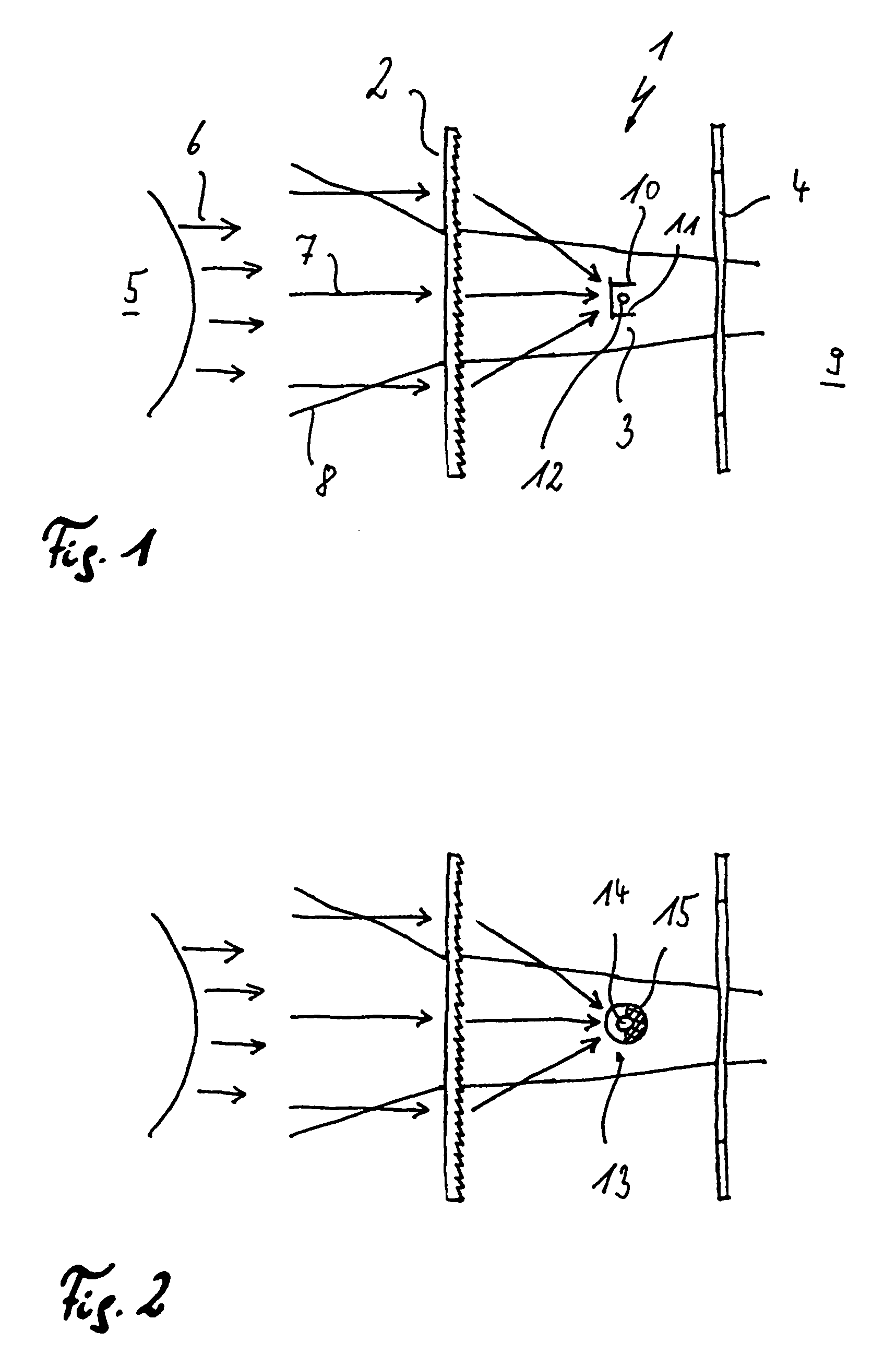
[0028]Turning now to the drawing, and in particular to FIG. 1, there is shown schematically a first embodiment of a light element according to the invention, generally designated by reference numeral 1 and including a translucent surface 2 and an energy conduit 3. The energy conduit 3 in the illustrated exemplified embodiment is implemented as a photovoltaic element and located between the translucent surface 2 which is here a Fresnel lens, and a window pane 4.

[0029]The radiation 6 originating from the sun 5 strikes the translucent surface 2 partially as direct radiation 7 and partially as diffuse radiation 8. The Fresnel lens concentrates the direct radiation 7 on the photovoltaic collector 3, whereas the diffuse radiation 8 passes through the Fresnel lens and the window pane 4 located behind the Fresnel lens.

[0030]The Fresnel lens 2 can form a point image or a linear image, thereby concentrating the radiation onto a point-shaped or linear energy conduit 3. Moreover, the Fresnel le...


PUM


Abstract

A light element with a translucent surface includes an energy converter, wherein the translucent surface is so formed as to direct only that portion of the radiation onto the energy converter that impinges on the translucent surface. The energy converter may be a solar cell, a fluid line or a light guide. The light element is particularly suited for illuminating interior spaces with diffuse light.

Description

CROSS-REFERENCES TO RELATED APPLICATIONS[0001]This application is a continuation of prior filed copending PCT International application no. PCT / DE99 / 03164, filed Oct. 1, 1999.[0002]This application claims the priority of German Patent Application Serial No. 198 45 656.5, filed Oct. 5, 1998, the subject matter of which is incorporated herein by reference.BACKGROUND OF THE INVENTION[0003]The invention relates to light element with a translucent surface, and more particularly, to a light element that efficiently extract the direct as well as the diffuse portion of the optical radiation impinging on the translucent surface.[0004]Sunlight shining through windows, glass walls and roofs can be used to illuminate the interior of a room. However, a strong light intensity can oftentimes cause glare, an inhomogeneous light distribution as well as a severe temperature increases in the interior space. Conversely, blinds can block the light flux from reaching the building interior so that artific...

Claims


Application Information

Patent Timeline
IPC IPC(8): H01L31/058A01G9/14F24J2/04F24S23/00F24S23/30H01L31/054
CPCA01G9/1438F24J2/0433F24J2/067F24J2/085H01L31/0547H01L31/0543Y02E10/43Y02E10/44Y02E10/52Y02B10/20F24S20/63F24S23/12F24S23/31Y02A40/25Y02E10/40Y02P60/12A01G9/243A01G9/245
Inventor KLEINWACHTER, JURGEN
Owner POWERPULSE HLDG
Why Eureka
Try Eureka