

Algorithm for the automatic determination of optimal AV an VV intervals
a technology of automatic determination and optimal pacing interval, which is applied in the direction of electrotherapy, heart stimulators, therapy, etc., can solve the problems of atrial tachycardia, insufficient filling of left ventricle, and inability to achieve optimal pacing of both left and right ventricles at the same time, so as to achieve optimal cardiac output
- Summary
- Abstract
- Description
- Claims
- Application Information
AI Technical Summary
Benefits of technology
Problems solved by technology
Method used
Image

Examples
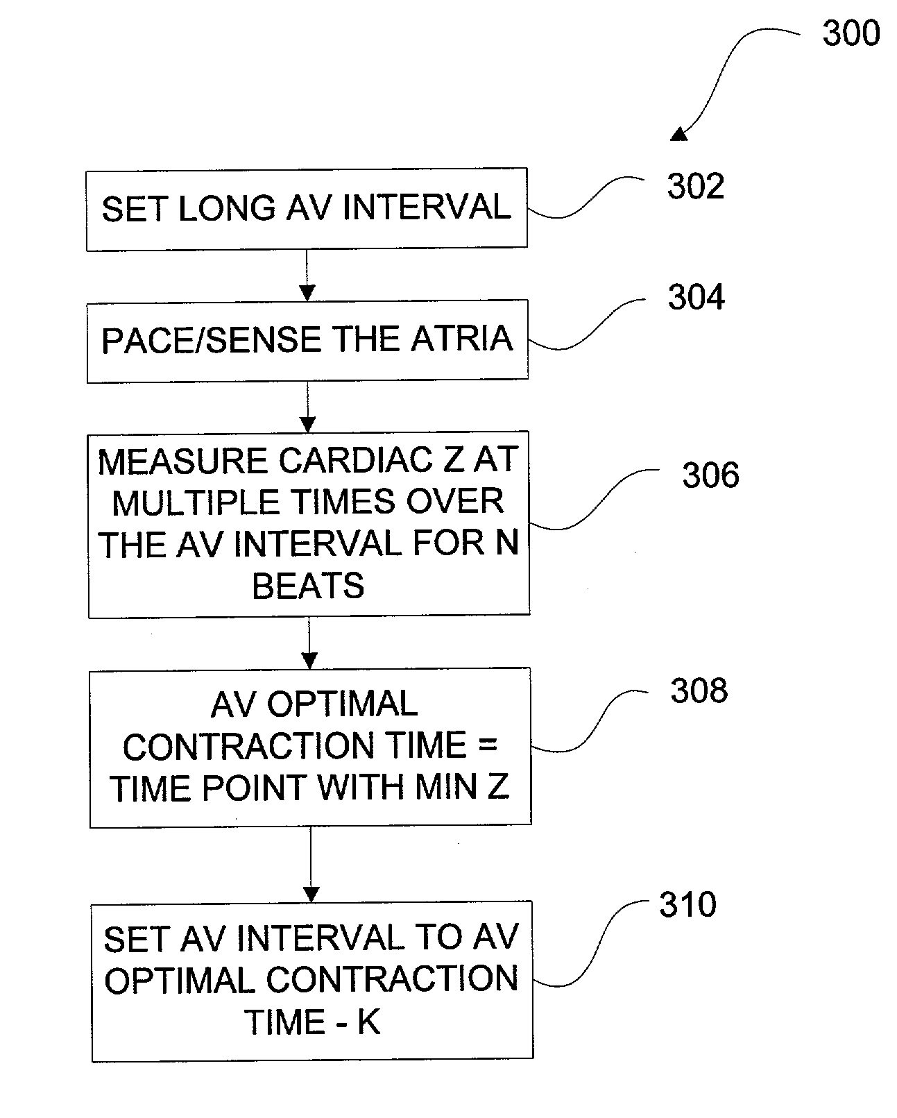
embodiment 300
[0060]The impedance measurement of embodiment 300 and the other methods discussed in the present application, can be measured as a vector across the best available leads present in the heart. In a bi-ventricular implanted pacing device, the impedance can be measured between a right ventricular electrode and a left ventricular electrode disposed in a cardiac vein. In one example, the impedance signal is stimulated between the left ventricular ring and the right ventricular ring and detected by the left ventricular tip and the right ventricular tip. The electrode pairs can be selected to maximize the impedance changes caused by the ventricular contractions and expansions. In another embodiment, having a ventricular lead, different electrodes disposed along the ventricular lead may be used to stimulate and sense the impedance vector.
[0061]FIG. 5A illustrates another embodiment 320A for optimizing the AV interval. While method 300 attempted to maximize ventricular expansion as measured ...
embodiment 340
[0071]FIG. 6 includes a flow chart for embodiment 340 which varies the VV interval to find the maximum impedance. The maximum impedance corresponds to the maximum ventricular contraction and minimum ventricular volume. Method 340 optimizes the VV interval indicating the amount of time by which the right ventricle leads or lags the left ventricle. The VV interval may also be viewed as having a separate atrium to right ventricle delay and a separate atrium to left ventricle delay. The VV interval may also be referred to as the inter-ventricle time difference.
[0072]In step 341, the VV interval can be initialized in some methods to 0. In step 342, the AV interval can be initialized and maintained at a constant, preferably, optimal AV interval. In some methods, the optimal AV interval as determined by methods such as method 300, 320A, or 320B can be used to set the optimal AV interval.
[0073]In step 344, the atrium A-event occurrence can be paced or sensed, then the first ventricle paced,...
embodiment 400
[0084]FIG. 8 illustrates an embodiment 400 for providing impedance data, to the interval optimization methods previously discussed. Method 400 is one example of a method for providing impedance data, which is preferably used in a clinical setting. In step 402, method 400 waits for a start signal. The patient is preferably supine, not moving, and has a regular breathing pattern. A treating physician can wait for the patient to be appropriately disposed then send a start signal from a programming unit, through a telemetry link, to the implanted pacing device. In step 402, the pacing device receives the start signal from the programmer, and proceeds to step 404.
[0085]In step 404, the implanted pacing device can automatically adjust pacing parameters as needed to carry out the interval optimization methods previously discussed to measure the impedance changes over one or more heartbeats. In the example illustrated, the impedance is measured over a single beat. With the impedance measure...
PUM
 Abstract
Description
Claims
Application Information