
Servo mounting system for direct drive of an aircraft control surface

a technology of direct drive and control surface, which is applied in the direction of actuating personally, toy aircraft, and energy-saving board measures, etc., can solve the problems of increasing the need for periodic maintenance and part replacement, increasing the geometry of a link or cable, and increasing the wear of the servo bearing and control hing

Inactive Publication Date: 2007-06-12
DURANT JOHN
View PDF33 Cites 15 Cited by
  • Summary
  • Abstract
  • Description
  • Claims
  • Application Information

AI Technical Summary

Benefits of technology

"This patent describes an improved system for controlling the flight of aircraft using servo drives. The invention solves problems associated with traditional servo drives by directly driving the control surfaces, reducing wear and tear, and improving control precision. The system uses a unique servo mount that is secured to the control surface, allowing for a simpler and more efficient drive mechanism. The mount can be installed in various ways, such as on the airframe or control surface, and is connected to the control surface through a coupler. The direct drive system has advantages over traditional linkage systems, including no linear loads, no lost motion, and no lost force due to friction. It also reduces the size of the servo and the number of parts, improves control flutter resistance, and results in a cleaner aerodynamic design."

Problems solved by technology

There are several inherent problems with these linkage drive systems:(a) A linkage generates a linear load which must be absorbed by both the servo shaft bearings and the control surface hinges.
This load accelerates wear on the servo bearings and control hinges, thereby increasing the need for periodic maintenance and part replacement.(b) At large control surface deflections, the geometry of a link or cable becomes severe.(1 ) The effective lengths of the lever arms become shorter at high control deflections when the air loads are strongest.
This results in an exponentially increasing load on the servo and the control hinge.
The result is added weight, which has negative aircraft performance consequences.(2) At the extremes of control travel, linkage angularity results in non-linear control deflection rates.
Additionally, when force is applied through any mechanical assembly, there is deflection due to stress.
The end result of these factors is lost motion between the servo and the control surface.
Lost motion is detrimental for two reasons:(1) Lost motion allows air loads to deflect the control surface from the commanded position.
This reduces the precision control of the surface, thereby reducing effective control of the aircraft.(2) Lost motion reduces the overall stiffness of the control assembly, which increases the risk of control surface flutter.
Flutter is potentially catastrophic to the structural integrity of an aircraft.(e) By their nature, linkage elements located at the control surface introduce mass behind the hinge line.
This increases the weight of the surface, thereby increasing the tendency of the surface to flutter.
Larger counterweights must be used to compensate for the weight of the control drive component, thereby adding weight to the aircraft.
Even with the mentioned shortcomings, linkages were necessary in past endeavors because:(a) Early generation servos were underpowered, which required a properly designed linkage to increase the mechanical advantage of the servo over the control surface.(b) Early generation servos had limited adjustment capability and no ability to change the direction of shaft motion in relation to an input.
This method of directly driving the control surface has still not been used since current servo case design impedes doing so.
Though providing flexibility, the resulting design of the modern commercial servo is not at all suited to being mounted on the hinge line of a control surface.
The output shaft is near the middle of the servo body, which is an undesirable location for hinge line mounting as it causes the servo case to protrude significantly into the area occupied by the control surface.
The provided mounting tabs extend further into the control surface space, further obstructing control motion.
Because a large portion of the servo body, including half of the mounting tabs, is located past the hinge line, there is no obvious way to secure the servo to the aircraft.
The mounting tabs are placed in an inconvenient, normally inaccessible location, and are at an awkward angle when securing the servo at the hinge line.
In short, the standard shape and design of commercially available servos has precluded them from even being considered for hinge line mounting.

Method used


Image

  • Servo mounting system for direct drive of an aircraft control surface
  • Servo mounting system for direct drive of an aircraft control surface
  • Servo mounting system for direct drive of an aircraft control surface

Examples


Embodiment Construction

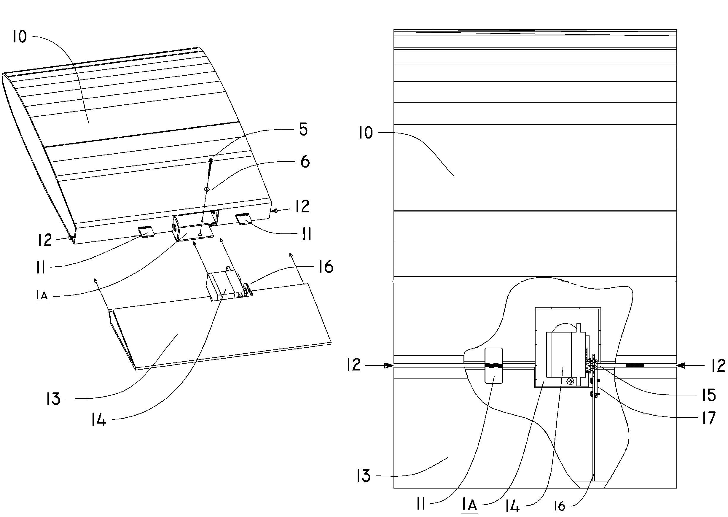
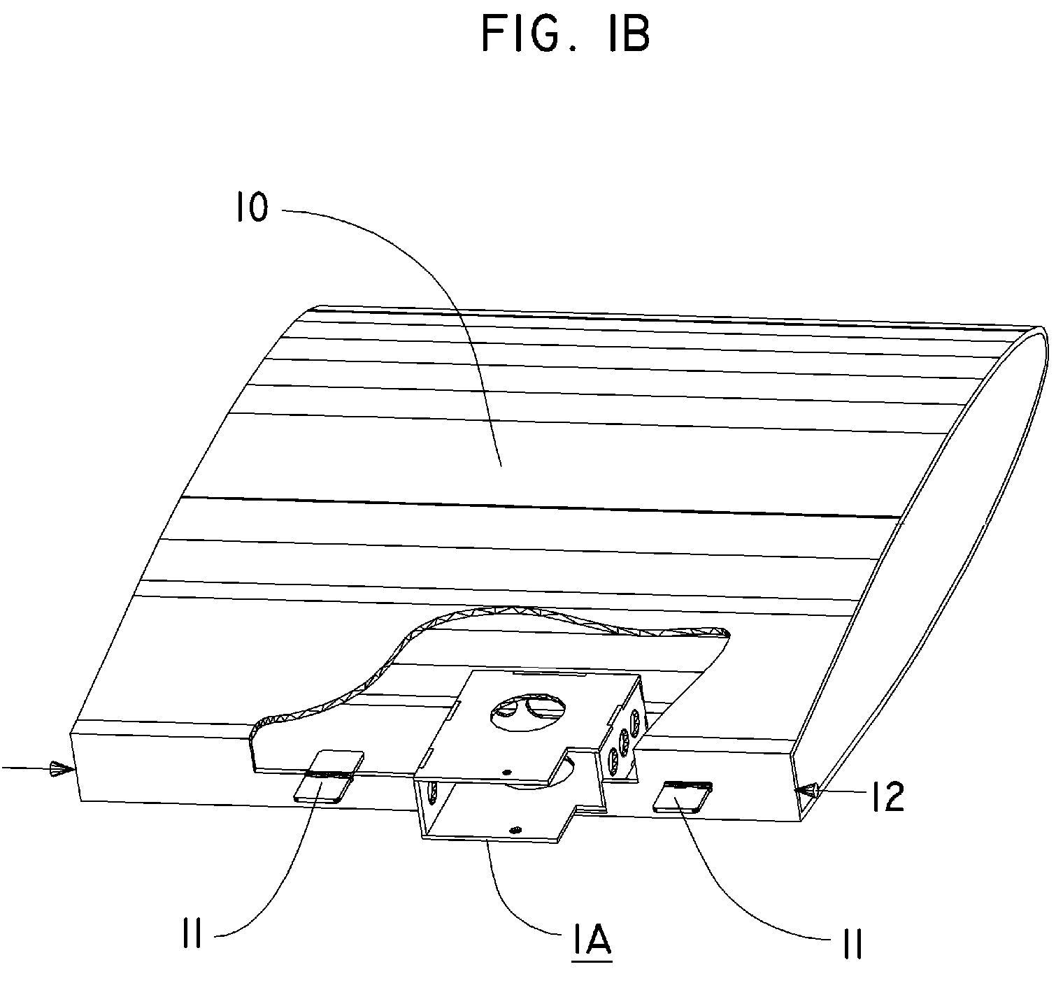
[0068]Although the direct servo drive mount is not limited to a particular aircraft size, material of construction, servo size or servo type—for ease of illustration the following description of embodiment will reference installations in a large model aircraft of 130 inches wingspan. The aircraft is a typical large scale model design, constructed of wood and composite materials. The horizontal stabilizer 23 employs a tubular metal spar 22 onto which the horizontal stabilizer 23 is mounted, permitting removal of the stabilizer as an assembly by sliding it off of the spar 22. The servo being mounted is a generic, commercially available electro-mechanical design, loosely termed in the model industry as “standard” size, with dimensions of 0.76″ by 2.25″ by 1.5″.

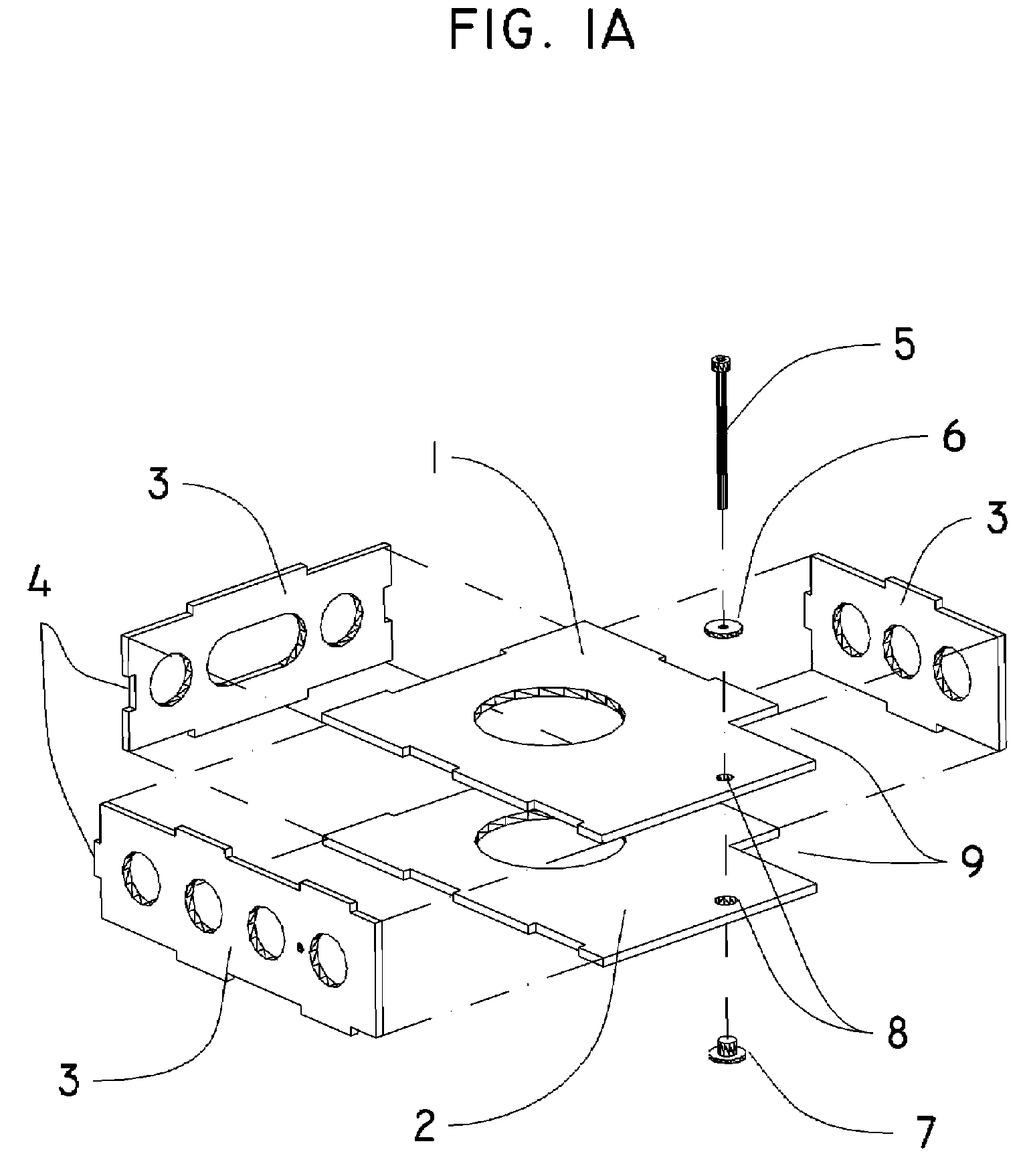
[0069]The direct drive servo mount in FIG. 1A is in the form of a hollow box which is sized to the dimensions of the particular servo being used. Shown are the upper plate 1, lower plate 2, and three sides 3. One side of the moun...


PUM


Abstract

This invention is a servo mounting system, which allows a servo with a rotating output shaft to directly power an aircraft control surface. A specially designed servo mount securely positions the servo with the central axis of its rotational output shaft on, and axially aligned with, the hinge line of the control surface it drives. The servo shaft and servo body are directly connected to the airframe and control surface, thereby conserving rotational motion while driving control movement. Electronic means are then used to control the neutral point and the limit of travel of the servo. The system eliminates lost motion without generating adverse linear loads within the drive assembly.

Description

SEQUENCE LISTING [0001]Not Applicable.CROSS-REFERENCE TO RELATED APPLICATIONS[0002]Not Applicable.STATEMENT REGARDING FEDERALLY SPONSORED RESEARCH OR DEVELOPMENT[0003]Not Applicable.THE NAMES OF THE PARTIES TO A JOINT RESEARCH AGREEMENT[0004]Not Applicable.INCORPORATION-BY-REFERENCE OF MATERIAL SUBMITTED ON A COMPACT DISC[0005]Not Applicable.BACKGROUND OF THE INVENTION[0006]1. Field of the Invention[0007]This servo mount design is related to the specific connection between the device or arrangement for controlling an aircraft and a controlled element.[0008]2. Description of Related Art including information disclosed under 37 CFR 1.97 and 1.98[0009]It is often necessary or desirable to power the motion of an aircraft control surface with an electro-mechanical servo. The most common use of servo powered flight controls is in the radio controlled aircraft hobby industry. There is also a rapidly growing market for commercial and military remotely piloted vehicles, which also employ the...

Claims


Application Information

Patent Timeline
Patent Type & Authority Patents(United States)
IPC IPC(8): B64C13/00B64C13/20B64C3/38B64C9/00
CPCA63H27/02B64C9/02B64C13/50Y02T50/32Y02T50/44Y02T50/545Y02T50/54Y02T50/30Y02T50/40Y02T50/50
Inventor DURANT, CECIL JOHN
Owner DURANT JOHN
Learn More