Fatigue-resistant components and method therefor

a technology of fatigue resistance and components, applied in the field of metal components, can solve the problems of reducing the life of parts, repair or replacement, and prone to cracking of various metallic components, and achieve the effect of reducing the propagation of cracks in metallic components

Active Publication Date: 2007-06-12
GENERAL ELECTRIC CO
View PDF7 Cites 23 Cited by
  • Summary
  • Abstract
  • Description
  • Claims
  • Application Information

AI Technical Summary

Benefits of technology

[0005]The above-mentioned need is met by the present invention, which according to one aspect provides a metallic component bounded by at least one peripheral edge. The component includes at least one elongated treated zone which is spaced away at an offset distance from and the peripheral edge. The entire thickness of the component within the treated zone is in a state of residual compressive stress, such that crack growth from the peripheral edge is resisted.
[0007]According to another aspect of the invention, a method of reducing crack propagation in metallic components includes providing a metallic component which is bounded by at least one peripheral edge, the component including at least one crack-prone area bounded in part by the peripheral edge. Pressure is applied to the component in at least one elongated treated zone, such that the entire thickness of the component within the treated zone is left a state of residual compressive stress, such that cracks are prevented from propagating out of the crack-prone zone.

Problems solved by technology

Various metallic components, such as gas turbine engine fan and compressor blades, are susceptible to cracking from fatigue and damage (e.g. from foreign object impacts).
This damage reduces the life of the part, requiring repair or replacement.
However, this process is relatively slow and expensive.

Method used


Image

  • Fatigue-resistant components and method therefor
  • Fatigue-resistant components and method therefor
  • Fatigue-resistant components and method therefor

Examples


Embodiment Construction

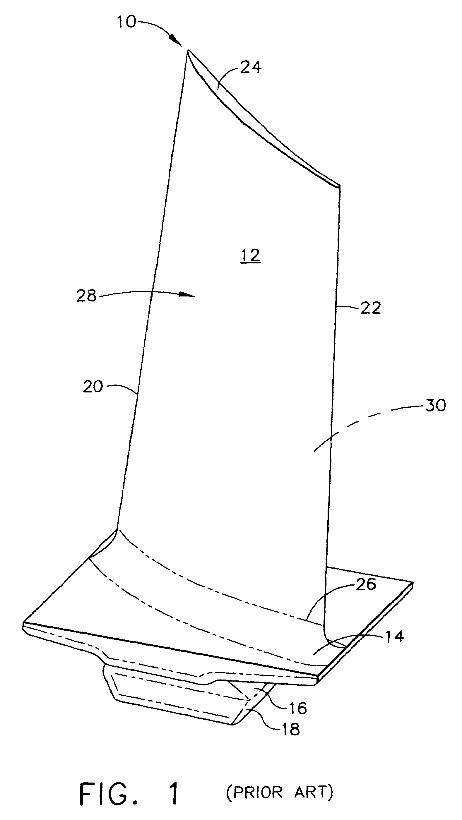
[0013]Referring to the drawings wherein identical reference numerals denote the same elements throughout the various views, FIG. 1 illustrates an exemplary gas turbine engine compressor blade 10. This component is used merely as an example, and the present invention is equally applicable to other types of metallic components susceptible to cracking from fatigue or damage, such as compressor stator vanes, fan blades, turbine blades, shafts and rotors, stationary frames, actuator hardware and the like. The compressor blade 10 comprises an airfoil 12, a platform 14, and a shank 16. In this particular example the shank 16 includes a dovetail 18 for being received in a slot of a rotating disk (not shown). The airfoil 12 has a leading edge 20, a trailing edge 22, a tip 24, a root 26, a suction side 28, and a pressure side 30.

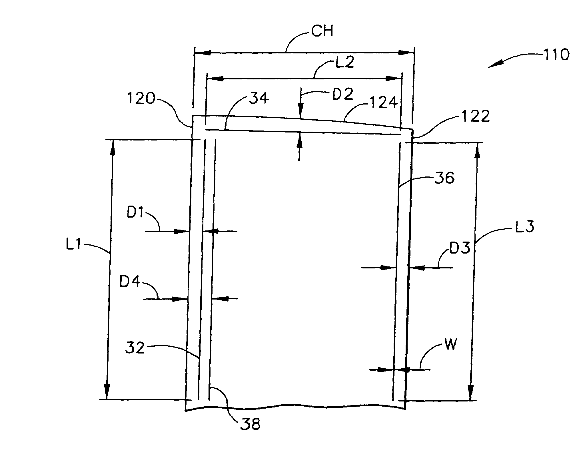
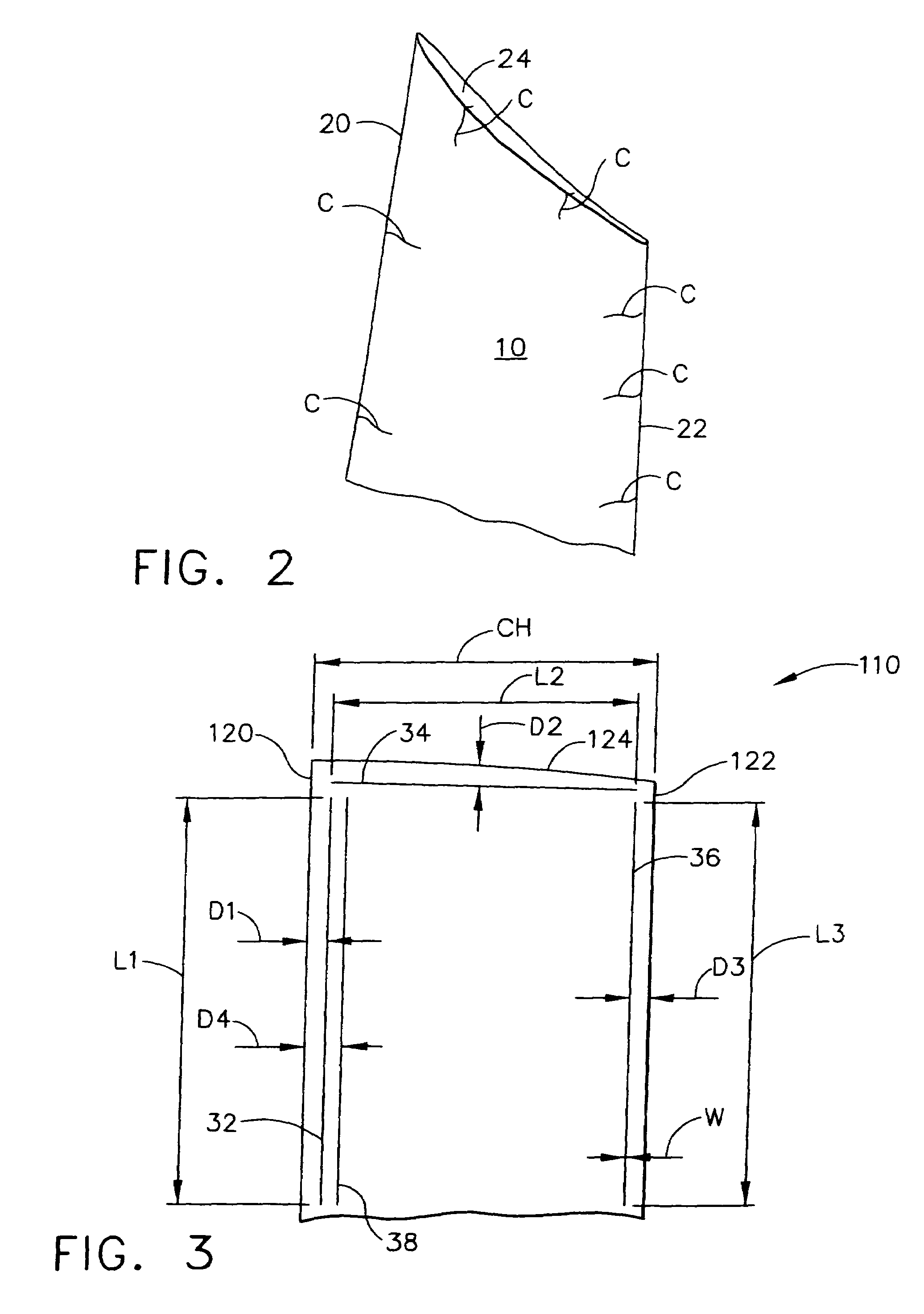
[0014]FIG. 2 shows an enlarged portion of the compressor blade 10. Certain areas of the compressor blade 10 are “crack-prone” or particularly subject to crack initiat...


PUM

PropertyMeasurementUnit
widthaaaaaaaaaa
offset distanceaaaaaaaaaa
offset distance D1aaaaaaaaaa

Abstract

A metallic component is by at least one peripheral edge. The component includes at least one elongated treated zone having a length substantially greater than its width. This treated zone is spaced away from and disposed generally parallel to the peripheral edge of the component and the entire thickness of the component within the treated zone is in a state of residual compressive stress. Crack growth from the edge due to fatigue or damage is resisted.

Description

BACKGROUND OF THE INVENTION[0001]This invention relates generally to metallic components and more particularly for a method of producing fatigue-resistant and damage-tolerant metallic components.[0002]Various metallic components, such as gas turbine engine fan and compressor blades, are susceptible to cracking from fatigue and damage (e.g. from foreign object impacts). This damage reduces the life of the part, requiring repair or replacement.[0003]It is known to protect components from crack propagation by inducing residual compressive stresses therein. Methods of imparting this stress include shot peening, laser shock peening (LSP), pinch peening, and low plasticity burnishing (LPB). These methods are typically employed by applying a “patch” of residual compressive stresses over an area to be protected from crack propagation, for example a leading edge of a gas turbine engine compressor blade. However, this process is relatively slow and expensive. This procedure also modifies area...

Claims


Application Information

Patent Timeline
Patent Type & Authority Patents(United States)
IPC IPC(8): F01D5/14
CPCB23P6/002B23P6/045B23P9/02F01D5/286F01D5/005Y10T428/12056F05D2230/90F05D2230/80
Inventor BRODERICK, THOMAS F.WOODFIELD, ANDREW P.LOMBARDO, DALE ROBERTMONCELLE, PAUL ROBERTDINGWELL, WILLIAM TERRENCE
Owner GENERAL ELECTRIC CO
Why Eureka
Try Eureka