Portable vapor diffusion coefficient meter

a vapor diffusion coefficient and portable technology, applied in the field of subsurface environmental remediation of underground sites, can solve the problems of inability to accurately detect the vapor diffusion coefficient, the physical properties used in the codes, and the cost and time-consuming of current methods

Active Publication Date: 2007-06-12
SANDIA NAT LAB
View PDF14 Cites 50 Cited by
  • Summary
  • Abstract
  • Description
  • Claims
  • Application Information

AI Technical Summary

Benefits of technology

[0013]An apparatus for measuring the effective vapor diffusion coefficient of a test vapor diffusing through a sample of porous media contained within a test chamber. A chemical sensor measures the time-varying concentration of vapor that has diffused a known distance through the porous media. A data processor contained within the apparatus compares the measured sensor data with analytical predictions of the response cur

Problems solved by technology

Current methods are costly and time-intensive, and limitations in sampling and analytical techniques exist.
However, the physical properties that are used in these codes, such as vapor diffusion coefficients and gas-phase permeabilities, are often unknown due to a lack

Method used


Image

  • Portable vapor diffusion coefficient meter
  • Portable vapor diffusion coefficient meter
  • Portable vapor diffusion coefficient meter

Examples


first embodiment

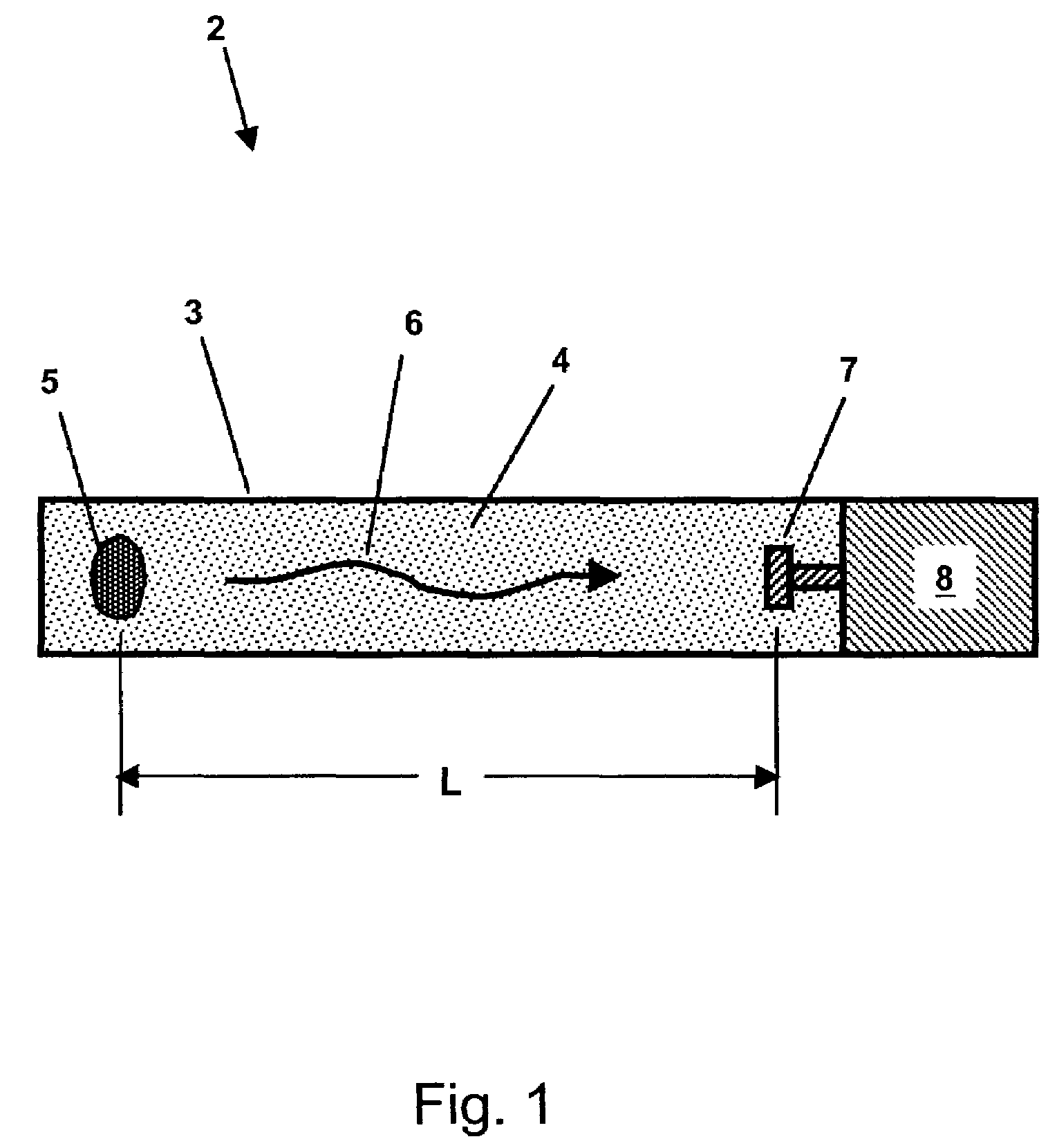
[0027]FIG. 1 shows a schematic cross-section view of a vapor diffusion coefficient meter, according to the present invention. Diffusion meter 2 comprises test chamber 3 that may be filled with a sample of porous media 4 to be tested. Means for introducing test vapor 5 may be located at one end of test chamber 3, and may comprise a cotton ball or other sponge-like material soaked with liquid NAPL or other volatile substance that readily emits test vapor 6. Test vapor 6 diffuses inside of test chamber 3 through porous media 4, eventually reaching sensor means 7, which is located at a distance, L, from the source of test vapor 5. Sensor means 7 is sensitive to the presence of test vapor 6, and produces a signal (in essentially real-time) that is proportional to the vapor's concentration. The signal generated by sensor means 7 is communicated to data processing means 8, which records the measured time-varying concentration of the test vapor and then calculates an effective vapor diffusi...

second embodiment

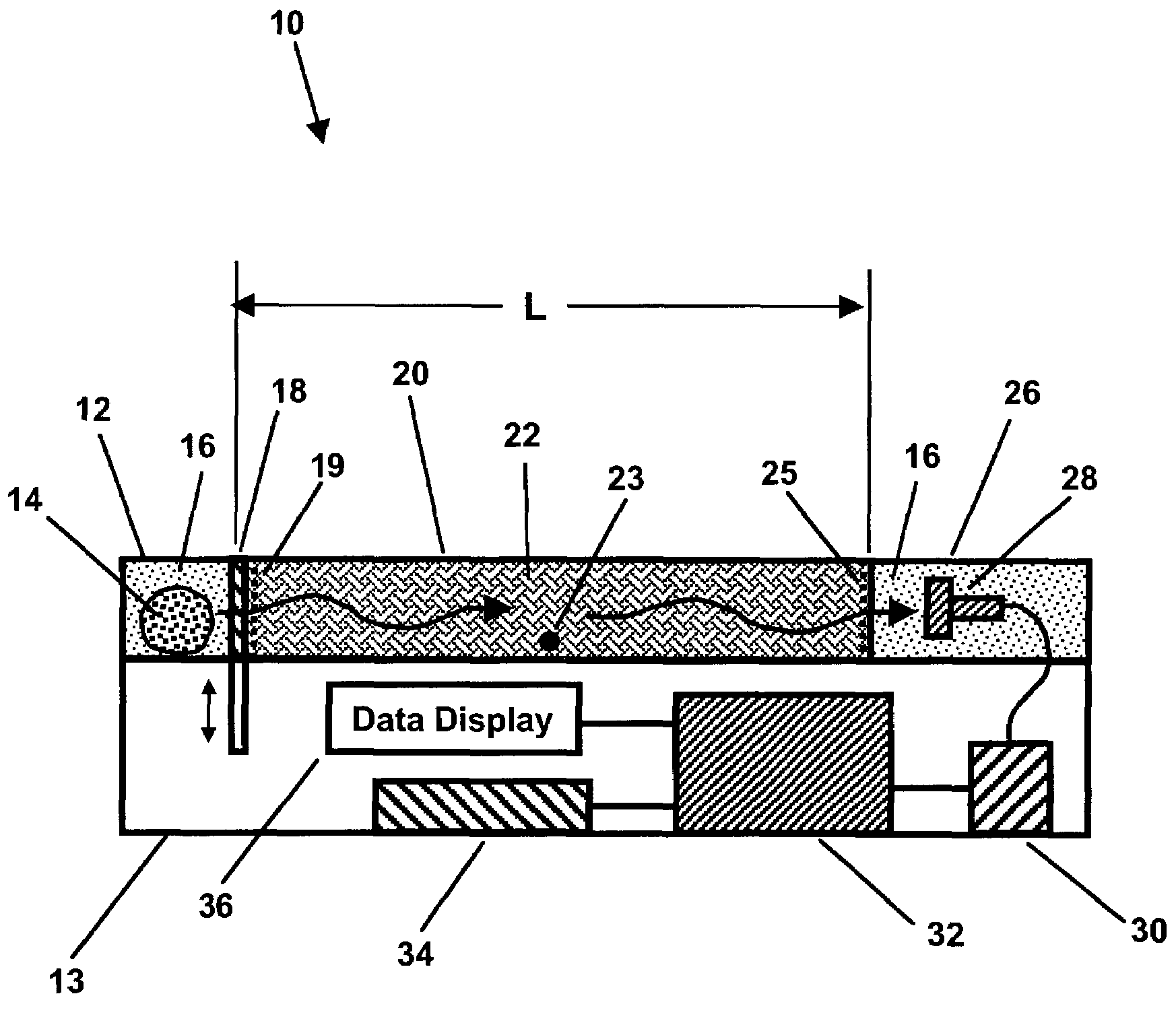
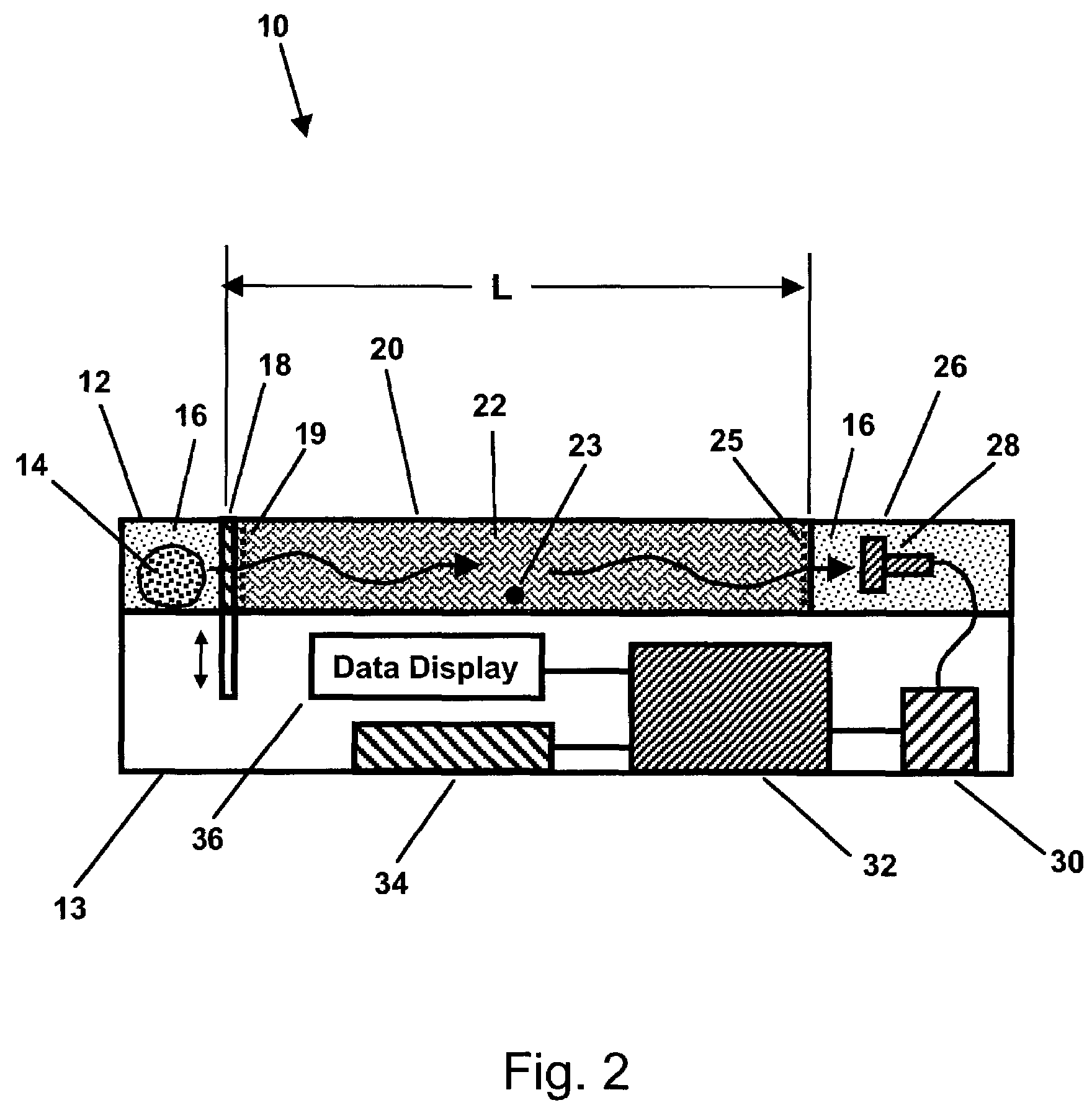
[0048]FIG. 2 shows a schematic cross-section view of a vapor diffusion coefficient meter, according to the present invention. Diffusion meter10 comprises a source chamber 12 for holding vapor source 14, which emits test vapor 16. Vapor source 14 may comprise, for example, a cotton ball or other sponge-like material loaded or soaked with a volatile liquid contaminant (e.g., NAPL) that emits vapors 16. Test chamber 20 may be filled with porous test media 22. Movable partition 18, such as an automatic or manually-operated gate valve with compliant seals, may be used to separate source chamber 12 from test chamber 20. Chemical sensor 28 may be housed inside detector chamber 26. The length, L, of test chamber 20 is approximately equal to the length of porous test media 22 in this embodiment. Alternatively, test chamber 20 may comprise mechanical means for adjusting the length of porous media 22 to be less than the length of test chamber 20, such as a plunger or piston with penetrations f...

third embodiment

[0085]FIG. 8 shows a schematic cross-section view of a vapor diffusion coefficient meter, according to the present invention. Diffusion meter 110 may additionally comprise upstream pump 138 and, optionally, downstream pump 146, for actively forcing the flow of a purge fluid (e.g., gas, vapor, or liquid) through test chamber 20. Pumps 138 and / or 146 may comprise a fan, compressor, vacuum pump, or liquid pump, as is well-known in the art. Movable partitions 166 and 118 may be used to control the rate of purge fluid flowing. The purge fluid (e.g., air, oxygen, ozone, air plus ozone, water, nitrogen, helium, and combinations thereof) may be used to purge test vapor 116 from test chamber 122 (and, possibly, detector chamber 126) after each test, which would allow multiple runs to be performed in rapid succession using the same vapor source 14. For example, when movable partition 166 is closed and movable partition 118 is open, then gas inlet tube 164 and control valve 162 may be opened t...


PUM

PropertyMeasurementUnit
Massaaaaaaaaaa
Lengthaaaaaaaaaa
Temperatureaaaaaaaaaa

Abstract

An apparatus for measuring the effective vapor diffusion coefficient of a test vapor diffusing through a sample of porous media contained within a test chamber. A chemical sensor measures the time-varying concentration of vapor that has diffused a known distance through the porous media. A data processor contained within the apparatus compares the measured sensor data with analytical predictions of the response curve based on the transient diffusion equation using Fick's Law, iterating on the choice of an effective vapor diffusion coefficient until the difference between the predicted and measured curves is minimized. Optionally, a purge fluid can forced through the porous media, permitting the apparatus to also measure a gas-phase permeability. The apparatus can be made lightweight, self-powered, and portable for use in the field.

Description

CROSS-REFERENCE TO RELATED APPLICATIONS[0001]This application is a continuation-in-part of U.S. application Ser. No. 10 / 152,597 filed May 22, 2002, “Waterproof Microsensor for In-Situ Monitoring of Volatile Compounds”, by Clifford K. Ho, et al., which is incorporated herein by reference. This application claims the benefit of U.S. Provisional application Ser. No. 60 / 335,644 filed Oct. 25, 2001, “Characterization Methods for Real-Time In-Situ Sensing of Volatile Contaminants”, by Clifford K. Ho, which is incorporated herein by reference. This application is related to co-pending application by Clifford K. Ho, “Automated Monitoring and Remediation System for Volatile Subsurface Contaminants Using In-Situ Sensors”. This application is also related to application Ser. No. 10 / 280,258 by Clifford K. Ho, “Methods for Characterizing Subsurface Volatile Contaminants Using In-Situ Sensors”, which issued as U.S. Pat. No. 7,003,405 on Feb. 21, 2006.FEDERALLY SPONSORED RESEARCH[0002]The United S...

Claims


Application Information

Patent Timeline
IPC IPC(8): B32B5/02B32B27/04B32B27/12G01N21/00G01N7/00
CPCG01N13/00G01N2013/003Y10T436/25875Y10T436/118339Y10T436/11Y10T436/117497
Inventor HO, CLIFFORD K.
Owner SANDIA NAT LAB
Why Eureka
Try Eureka