Non-isolated power conversion system having multiple switching power converters

a power conversion system and power converter technology, applied in the direction of automatic control, process and machine control, instruments, etc., can solve the problems of difficult short turn-on periods of switches, and difficulty in generating very narrow turn-on switch activation control signals, etc., to reduce current stresses in the power conversion system

Active Publication Date: 2007-06-12
DELTA ELECTRONICS INC
View PDF12 Cites 49 Cited by
  • Summary
  • Abstract
  • Description
  • Claims
  • Application Information

AI Technical Summary

Benefits of technology

[0011]The present invention discloses different embodiments of non-isolated multi-stage switching power converters that provide high conversion ratios in response to the duty cycle associated with a switching cycle of cascaded power converters. In one embodiment, the power converter is a step-down power converter that provides regulated low-voltage output at an output stage from high-voltage input at an input stage. The step-down power conversion system provides a power conversion ratio less than or equal to one. According to these embodiments, the step-down power conversion system of the invention operates with larger duty cycle that produces wider switch activation control signals applied to switches that lower voltage stresses and reduce switching losses.
[0012]In another embodiment, the power conversion system of the present invention is a step-up power conversion system that provides regulated high-voltage output at an output stage from a low-voltage input at an input stage. The step-up power conversion system provides a power conversion ratio greater than or equal to one. According to these embodiments, the step-up power conversion system of the invention operates with smaller duty cycle that reduces switch conduction losses.
[0019]In yet further detailed features of the invention, the circuits of this invention can be implemented in a variety of ways. Specifically, multiple pairs of switches, diode rectifiers, and capacitors can be connected in parallel to reduce the current stresses in the power conversion system. Also, the power conversion system could be connected in parallel for high current applications.

Problems solved by technology

Because the duty cycle of the conventional buck converter is proportional to the conversion ratio of input / output voltage in applications that use high switching frequencies for providing high conversion ratios, the turn-on periods of the switches are extremely short.
Consequently, extremely narrow switch activation pulses are necessary for maintaining very short duty cycles.
Generating very narrow turn-on switch activation control signals, however, is difficult because of parasitic components that are associated with the switching devices and the switch activation circuit.
In addition, a conventional buck converter in applications that require a high-voltage conversion ratio suffers from a serious efficiency degradation.
Usually, high-voltage switching devices are more expensive and have greater conduction losses in comparison with low-voltage-rated switching devices.
The efficiency of the conventional buck converter is further degraded by a severe switching loss.
Because the duty cycle of the conventional boost converter should be maximized to provide a very large conversion ratio of input / output voltage, the turn-on periods of the switches are extremely long.
Consequently, extremely long switch conduction period increases conduction losses and lowers converter efficiency.

Method used


Image

  • Non-isolated power conversion system having multiple switching power converters
  • Non-isolated power conversion system having multiple switching power converters
  • Non-isolated power conversion system having multiple switching power converters

Examples


Embodiment Construction

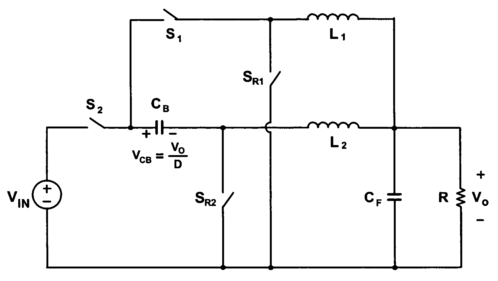
[0052]The power conversion system of the present invention is described in terms of multiple switching power converter stages that provide conversion ratios in response to a duty cycle associated with a switching cycle. The multiple switching power converter stages are cascaded in accordance with the present invention.

[0053]In one embodiment, the power conversion system of the invention comprises a step-down power conversion system that provides regulated low-voltage output at an output stage from a high-voltage input at an input stage. The step-down power conversion system provides a power conversion ratio less than or equal to one. According to these embodiments, the power conversion system of the invention operates with larger duty cycle that produces wide switch activation control signals applied to switches that lower voltage stresses and reduce switching losses.

[0054]In another embodiment, the power conversion system of the present invention is a step-up power conversion syste...


PUM


Abstract

A non-isolated power conversion system has an input stage and an output stage. A plurality of cascaded switching power converter stages are coupled between the input stage and the output stage. Each of the plurality of switching power converter stages has at least one switch that is activated in accordance with a duty cycle associated with a switching cycle. At least one energy storage device temporarily stores energy that is proportional to the duty cycle during the switching cycle for delivery to the output stage.

Description

BACKGROUND OF THE INVENTION[0001]1. Field of the Invention[0002]This invention generally relates to power conversion systems, more particularly to non-isolated power conversion systems that use multiple switching power converters.[0003]2. Description of the Prior Art[0004]Isolated and non-isolated power conversion systems are known. Isolated power supplies generally use a transformer for isolating an input power stage from an output power stage through primary and secondary windings. Non-isolated power conversion systems usually use cascaded switching power converter stages associated with one or more switching cycles.[0005]Known non-isolated power converters have been used in AC-DC, AC-AC, DC-AC, and DC-DC applications. Examples of such converters include buck converters, boost converter and buck-boost converters that can be implemented using various switching power conversion topologies. In such topologies, the input / output conversion ratios are determined according to duty cycles...

Claims


Application Information

Patent Timeline
Patent Type & Authority Patents(United States)
IPC IPC(8): G05F1/00
CPCH02M3/1584H02M3/005
Inventor JANG, YUNGTAEKJOVANOVI, MILAN
Owner DELTA ELECTRONICS INC
Why Eureka
Try Eureka