Controlled oscillator

a technology of controlled oscillators and oscillators, which is applied in the direction of oscillation generators, modulation, pulse techniques, etc., can solve the problem of difficult implementation of certain oscillator circuits on an i

Active Publication Date: 2007-06-12
SILICON LAB INC
View PDF7 Cites 42 Cited by
  • Summary
  • Abstract
  • Description
  • Claims
  • Application Information

AI Technical Summary

Problems solved by technology

However, depending on various factors such as operating frequency and fabrication technology, for example, it may be difficult to implement certain oscillator circuits on an IC.

Method used


Image

  • Controlled oscillator
  • Controlled oscillator
  • Controlled oscillator

Examples


Embodiment Construction

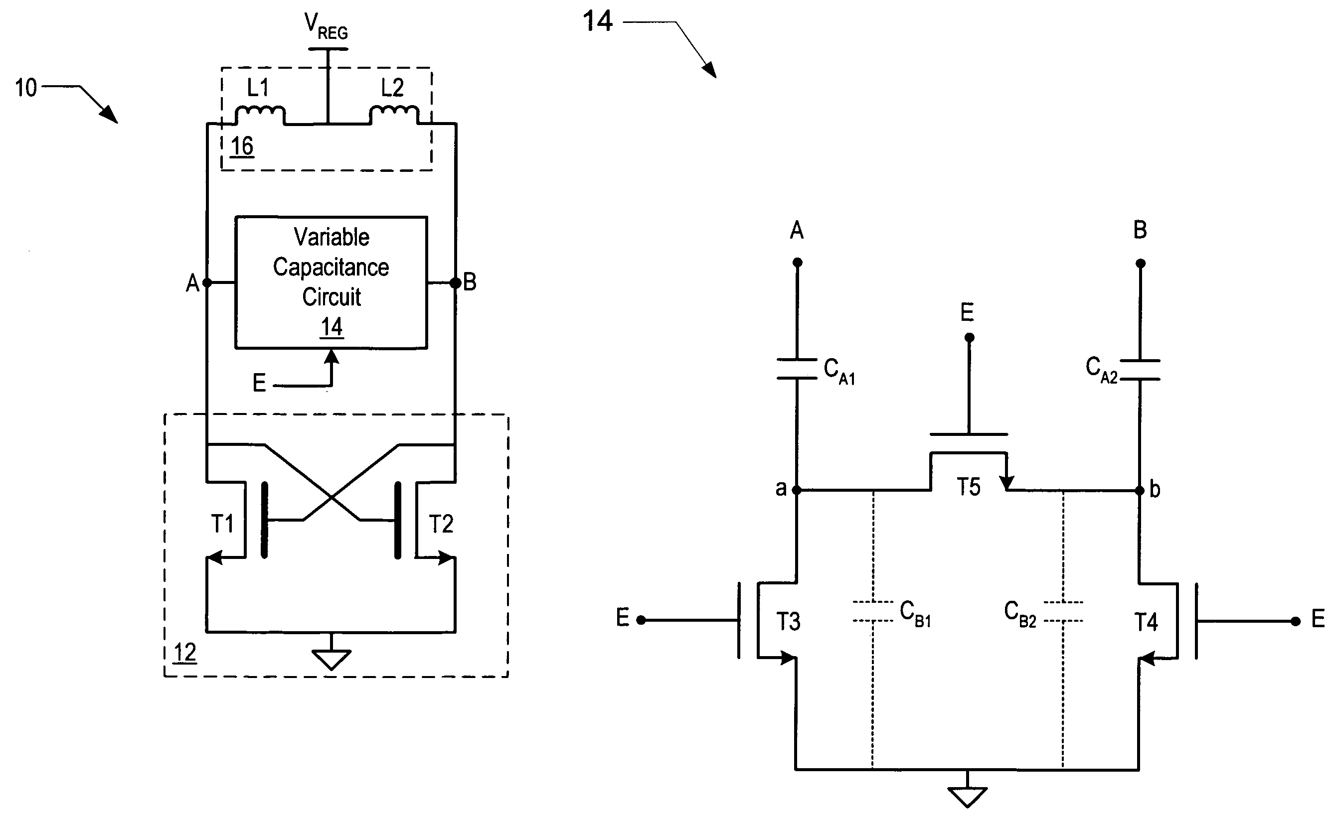
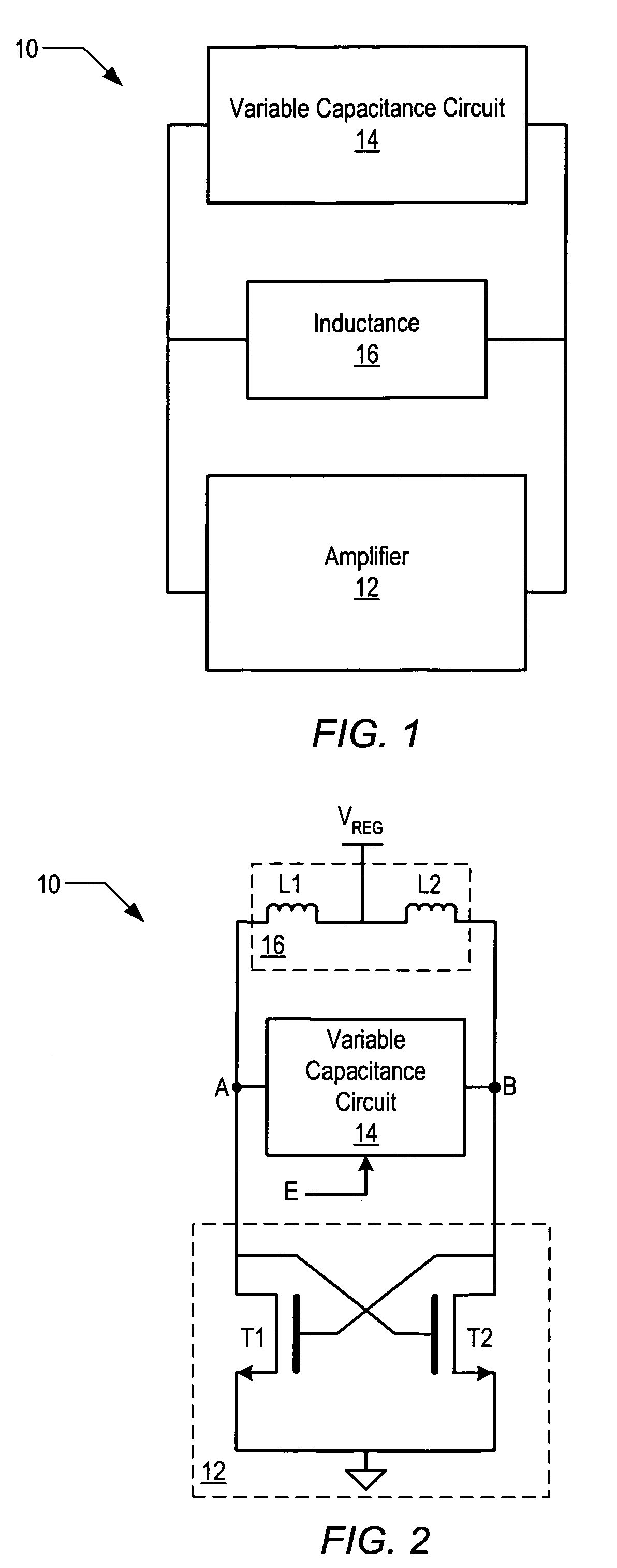
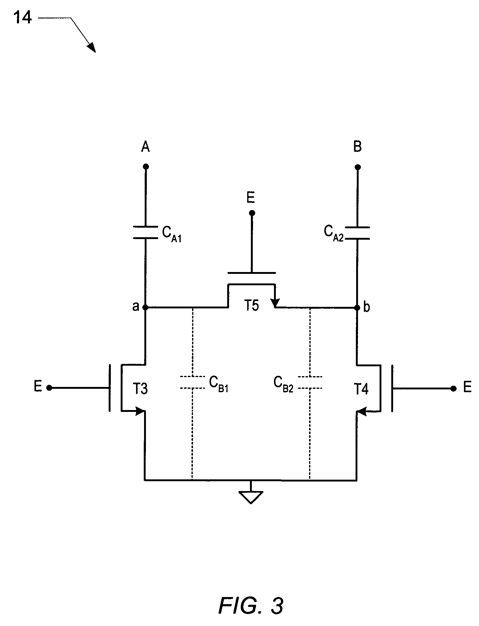
[0014]Turning now to FIG. 1, a simplified block diagram of one embodiment of an oscillator is shown. Oscillator 10 includes a variable capacitance circuit 14 coupled to an inductance 16 that is, in turn coupled to amplifier 12. It is noted that one or more portions of oscillator 10 may be manufactured on a semiconductor integrated circuit.

[0015]In the illustrated embodiment, oscillator 10 may oscillate at one or more frequencies that may be determined, at least in part, by the combination of inductance and capacitance (i.e., an LC tank) provided by inductance 16 and variable capacitance circuit 14, respectively. Amplifier 12 may provide the amplification necessary to drive and sustain oscillations.

[0016]In one embodiment, oscillator 10 is referred to as a controlled oscillator since an output frequency of oscillator 10 may be controlled by both digital and analog means. For example, as will be described in greater detail below, the output frequency of oscillator 10 may be adjusted b...


PUM


Abstract

A controlled oscillator circuit includes an amplifier including a first transistor coupled between a first node and a reference node, and a second transistor coupled between a second node and the reference node. The gate of first transistor and the gate of the second transistor may be cross-coupled. The oscillator may also include one or more variable capacitance circuits coupled between the first node and the second node, each including a first capacitor coupled between the first node and a third node, and a second capacitor coupled between the second node and a fourth node. Each variable capacitance circuit may also include a third, a fourth and a fifth transistor interconnected to selectively couple the first and second capacitors to the reference node. The third, fourth and fifth transistors may be low voltage transistors and the first and the second transistors may be high voltage transistors.

Description

BACKGROUND OF THE INVENTION[0001]1. Field of the Invention[0002]This invention relates to semiconductor integrated circuits and, more particularly, to the topology and structure of oscillators manufactured on semiconductor integrated circuits.[0003]2. Description of the Related Art[0004]Many wireless communication devices such as mobile telephones, for example, employ a number of integrated circuits (ICs) to perform various functions. One such function is the generation of high frequency signals for use during transmission and reception. As such, some communication devices may include one or more frequency synthesizer circuits such as a phase locked loop (PLL), for example, to generate the desired high frequency signals.[0005]A frequency synthesizer typically includes a controlled oscillator circuit, such as voltage-controlled oscillators (VCO), for example, which may be used within the control loop of a synthesizer. It may be generally desirable to integrate the oscillator circuit ...

Claims


Application Information

Patent Timeline
Patent Type & Authority Patents(United States)
IPC IPC(8): H03B5/00
CPCH03B5/1228H03B5/1212H03B5/124H03B2201/0266H03B5/1265
Inventor MARQUES, AUGUSTO M.WILLINGHAM, SCOTT D.
Owner SILICON LAB INC
Why Eureka
Try Eureka