Wedge shaped suture anchor and method of implantation

a suture anchor and wedge-shaped technology, applied in the field of surgical implements, can solve the problems of increasing the load and stress placed on, generating numerous bone tunnels, and joint injuries with corresponding damage to associated soft tissue, so as to improve the rotation of the device and the effect of better dispersing the force acting on the devi

Inactive Publication Date: 2007-06-19
DEPUY MITEK INC
View PDF73 Cites 52 Cited by
  • Summary
  • Abstract
  • Description
  • Claims
  • Application Information

AI Technical Summary

Benefits of technology

[0009]The device of the present invention calls for an implantable apparatus for wedging within an opening formed within a bone. The apparatus comprises a body which defines a perimeter and said perimeter defining at least one biting edge. A hole is defined by the body through which a suture is received for attachment through the device to the bone. The hole defined by the body may be nearer to one side of the perimeter in order to provide an imbalance of force to increase rotation of the device during the implantation procedure. The body in cross-section may have a perimeter which is substantially in the shape of a triangle, trapezoid or parallelogram. In this way the body may have two slides which diverge in a direction away from said hole, such that the rotation causes an edge formed by one of such sides to bite into the soft cancellous layer of the bone. In order to better distribute the forces acting on the device, the sides may be rounded so that the rounded edge will match with the size of the bore hole provided in the bone. In this way, maximum contact of the edge with the side of the hole in the bone is provided.
[0010]The edge may be formed by the intersection of planar or rounded sides or a combination of planar and rounded sides in order to optimize the biting action of the edge. The edge may also be provided with a single engaging tooth or a plurality of engaging teeth in order to improve the holding power, biting and / or placement of the device. The device may be triangular in shape and thus formed by three mutually adjacent sides.
[0012]The body may be made of any medical grade material and the stem may be made of a different medical grade material. The body and stem may be joined by a frangible portion which could be formed, for example, by two intersecting web portions in order to provide stability to the device during insertion while still providing the weakness necessary for fracture of the area.
[0017]The insertion device may include a stabilizing portion to prevent excessive premature rotation of the device and thus prevent premature fracture of any frangible portion of the stem. This however is not necessary in the method where the device is attached to the stem through an interference or frictional fit and the stem is merely removed from an opening in the device during the method of implantation.
[0023]And in another form of the invention, the suture anchor can comprise a substantially wedge-shaped body having a smaller distal end and a larger proximal end, the body having means thereon for retaining a suture, and a boundary surface having means therein for releasable connection to an inserter shaft; the means for releasable connection to an inserter shaft comprising a smooth-walled counterbore in the boundary surface, and a second bore in a bottom of the counterbore, the second bore being adapted to receive a threaded end portion of the inserter shaft and to be threadedly engaged thereby, and the counterbore being adapted to receive a cylindrically-shaped flexible tip portion of the inserter shaft; wherein flexing of the inserter shaft tip portion is permitted by the counterbore substantially without disturbing the engagement of the threaded end portion of the inserter shaft with the second bore.

Problems solved by technology

These types of activities may increase the loads and stress placed upon joints, sometimes resulting in joint injuries with corresponding damage to associated soft tissue.
This method, although effective, is a time consuming procedure resulting in the generation of numerous bone tunnels.
A known complication of drilling tunnels across bone is that nerves and other soft tissue structures may be injured by the drill bit or orthopaedic pin as it exits the far side of the bone.
Also, it is anatomically very difficult to reach and / or secure a suture / wire that has been passed through a tunnel.
When securing the suture or wire on the far side of the bone, nerves and soft tissues can become entrapped and damaged.
Although most suture anchors described in the art are made from non-absorbable materials, the use of absorbable suture anchors may result in fewer complications since the suture anchor is absorbed and replaced by bone over time.
In addition, the use of absorbable suture anchors may reduce the likelihood of damage to local joints caused by anchor migration.

Method used


Image

  • Wedge shaped suture anchor and method of implantation
  • Wedge shaped suture anchor and method of implantation
  • Wedge shaped suture anchor and method of implantation

Examples


Embodiment Construction

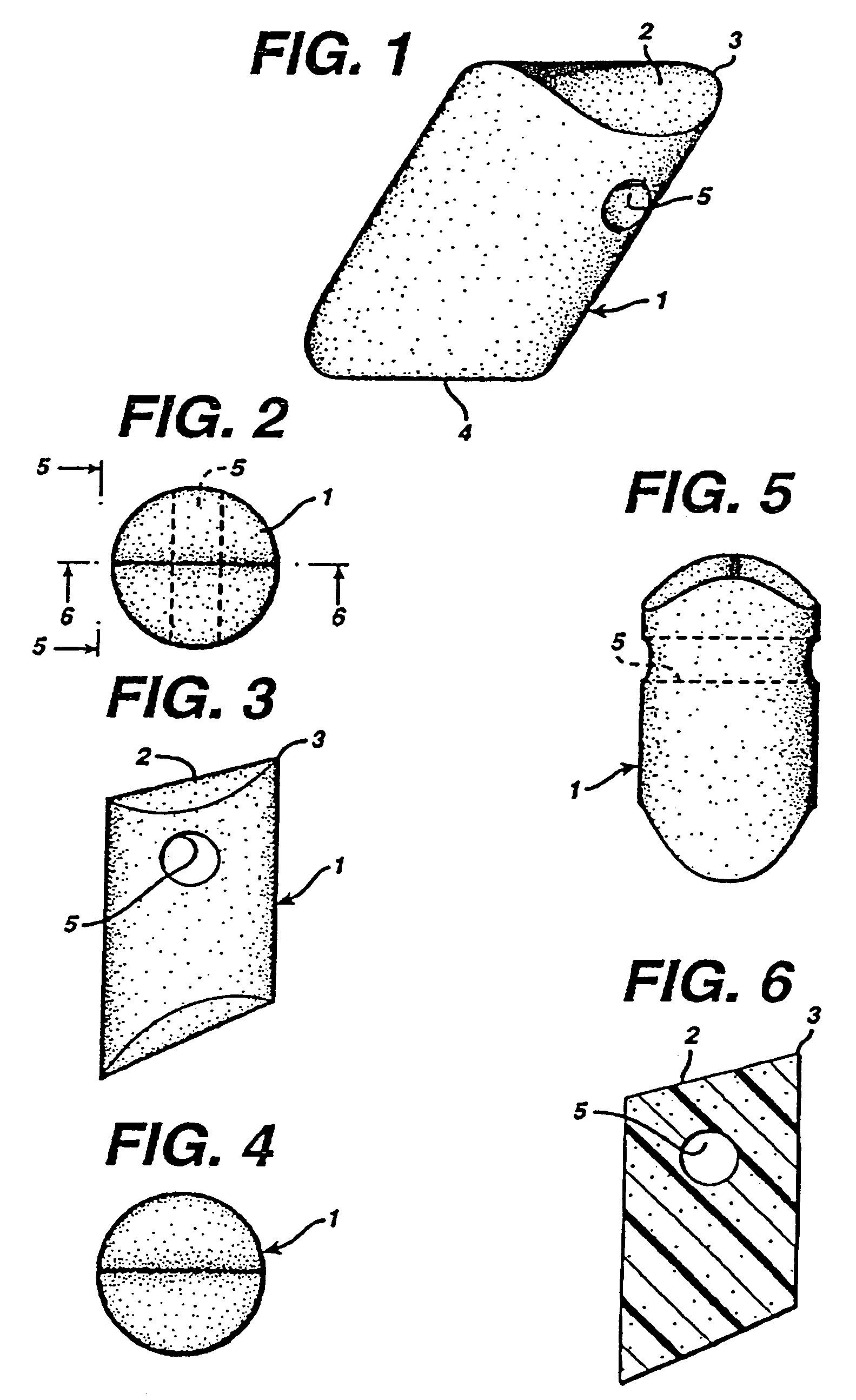
[0106]A first aspect of a suture anchor according to the present invention is a unitized suture anchor, particularly as shown in FIG. 1. The first embodiment of the invention will now be described with reference to the Figures. The suture anchor 1 has a first abutment end 2 and a second abutment end 3. The suture anchor has a substantially cylindrical cross-section as shown in FIG. 2 and the cylindrical longitudinal surface forms with the abutment end 2 a corner 4. The diameter of the suture anchor is sized smaller than the bore hole or opening in the bone receiving the suture anchor. This permits passage of the suture end(s) out of the opening. A suture opening 5 is defined by the body of the suture anchor 1. In an alternative embodiment shown in FIG. 3 the first abutment end 2 and second abutment end 3 are slightly tapered to a point or edge. This is due to the extruding process of formation as will be described below. The suture opening 5 is formed transverse to the longitudinal ...


PUM


Abstract

A suture anchor is described which in one form may be easily fabricated from extruded material by angular cuts and bore holes which provide an offset pulling force to the suture. In an alternate and preferred embodiment the suture anchor is injection molded having an annular displaced corner and abutment wall which act to seat the suture anchor firmly within a bore hole. Novel application means are also disclosed which hold the suture anchor on a frangible shaft for insertion and upon completion of the insertion permit fracture of the frangible portion and removal of the instrument. In another form of the invention, the suture anchor comprises a substantially wedge-shaped body having a smaller distal end and a larger proximal end, means thereon for retaining a suture, and means thereon for releasable connection to an inserter shaft; a boundary surface and a plow surface of the body intersecting to form a biting edge at the proximal end of the body; and the boundary surface and an abutment surface of the body intersecting to form a cam surface at the proximal end of the body; and the biting edge being adapted to be in engagement with a first wall portion of a bore in a bone and the cam surface being adapted to be in engagement with a second wall portion of the bore opposed to the first wall portion; wherein tension on the inserter shaft is operable to move the cam portion along the bore second wall portion and rotate the body in the bore such that the biting edge bites into the bore first wall portion to lock the body in the bore.

Description

[0001]This is a continuation of prior U.S. patent application Ser. No. 10 / 782,344, filed Feb. 19, 2004 by Jack S. Pedlick, Thu Anh Le, John DiGiovanni, Dennis D. Jamiolkowski, and Mark J. Suseck for WEDGE SHAPED SUTURE ANCHOR AND METHOD OF IMPLANTATION, which in turn is a continuation of U.S. patent application Ser. No. 09 / 923,996, filed Aug. 7, 2001 now U.S. Pat. No. 6,726,707 by Jack S. Pedlick, Thu Anh Le, John DiGiovanni, Dennis D. Jamiolkowski, and Mark J. Suseck for WEDGE SHAPED SUTURE ANCHOR AND METHOD OF IMPLANTATION, which in turn is a continuation of U.S. patent application Ser. No. 09 / 412,903, filed Oct. 5, 1999 now U.S. Pat. No. 6,270,518 by Jack S. Pedlick, Thu Anh Le, John DiGiovanni, Dennis D. Jamiolkowski, and Mark J. Suseck for WEDGE SHAPED SUTURE ANCHOR AND METHOD OF IMPLANTATION, which in turn is a continuation of U.S. patent application Ser. No. 08 / 630,389, filed Apr. 10, 1996 now U.S. Pat. No. 5,961,538 by Jack S. Pedlick, Thu Anh Le, John DiGiovanni, Dennis D. ...

Claims


Application Information

Patent Timeline
Patent Type & Authority Patents(United States)
IPC IPC(8): A61B17/04A61B17/00A61B17/06A61B17/56A61B19/00
CPCA61B17/0401A61B17/0482A61B2017/00424A61B2017/00455A61B2017/00862A61B2017/0409A61B2017/0414A61B2017/0458A61B2017/06057A61B2017/06142A61B2019/307A61B2019/444A61B2019/5437Y10S606/916A61B2090/037A61B90/92A61B2090/3937
Inventor PEDLICK, JACK S.LE, THU ANHDIGIOVANNI, JOHNJAMIOLKOWSKI, DENNIS D.SUSECK, MARK J.
Owner DEPUY MITEK INC
Why Eureka
Try Eureka