Earphone antenna, composite coil and coaxial cable used therefor, and wireless device provided with the earphone antenna

a wireless device and antenna technology, applied in the direction of earpiece/earphone cables, waveguide devices, resonance antennas, etc., can solve the problems of earphone antennas being susceptible to equipment noise noise, difficult to obtain a sufficient receiving sensitivity with these antennas, and reducing the service life of earphone antennas, so as to improve the reception sensitivity and shorten the antenna length. , the effect of shortening the antenna length

Inactive Publication Date: 2007-06-26
SONY CORP
View PDF9 Cites 17 Cited by
  • Summary
  • Abstract
  • Description
  • Claims
  • Application Information

AI Technical Summary

Benefits of technology

[0017]Therefore, according to the wireless device as claimed in claim 3, since the earphone antenna as claimed in claim 1 is used, the advantages provided by the earphone antenna can be enjoyed.
[0022]Hence, a dipole antenna that resonates at the fundamental frequency (e.g., 100 MHz) and further resonates with its harmonics (a third harmonic at, e.g., 300 MHz, a fifth harmonic at, e.g., 500 MHz, and a seventh harmonic at, e.g., 700 MHz) and a dipole antenna that resonates with signals having a specific frequency (e.g., 200 MHz) higher than a pre-set frequency (e.g., 100 MHz) and that excites with its harmonics (a third harmonic at, e.g., 600 MHz, and the like) are formed from the above-mentioned two pairs of audio / high-frequency dual-function signal lines. As a result, a sensitivity characteristic that exhibits relatively small variations in receiving sensitivity can be obtained over a wide frequency band, and thus no sensitivity adjustment of the earphone antenna is required at all in order to obtain the sensitivity characteristic.
[0023]Note that the loading coils shorten an antenna length required for resonance at the fundamental frequency (e.g., 100 MHz), to allow resonance to occur with signals having long wavelengths even with a short antenna length. As a result, the receiving sensitivity to low-frequency signals can be enhanced without unreasonably increasing the antenna length. This is an advantage that is not negligible.
[0024]Therefore, a sensitivity characteristic that exhibits relatively small variations in receiving sensitivity can be obtained over a wide frequency band, and thus no sensitivity adjustment of the earphone antenna is required at all in order to obtain the sensitivity characteristic.
[0026]Therefore, the antenna can be used for reception of high-frequency signals over a wide frequency band, and also it can as means for transmitting audio signals to the earphone units, whereby integration of the high-sensitivity, wide-band antenna with the earphone units becomes possible.
[0028]Therefore, according to the composite coil as claimed in claim 11, a plurality of coils can be formed in a size substantially equal to that of a single coil, whereby it contributes to a downsizing and weight reduction of devices using a plurality of coils. Particularly, if the above-mentioned respective coils constituting each of the above-mentioned composite coils are to be used as the respective loading coils in each of the above-mentioned left and right pairs of loading coils of the earphone antenna, they contribute to a downsizing and weight reduction of the earphone antenna, and thus inconvenience at the time of use of the earphone antenna can be reduced.

Problems solved by technology

It has been difficult to obtain a sufficient receiving sensitivity with these antennas.
However, giving no consideration to earphones, and these antennas have addressed an issue that signal lines to the earphones must be provided separately.
Further, the earphone antenna in which audio signal lines to earphones are integrated with an antenna has addressed the issue that the human body exerts serious influence upon a wireless device through the antenna due to the earphones directly touching the human body and the stability of reception is greatly compromised.
Furthermore, the fact that a matching section of the antenna and an equipment section, such as a tuner, are placed within the same equipment has imposed another problem that the earphone antenna is susceptible to noises of the equipment.
However, the fact is that no effective measures have been taken for that problem.
Furthermore, where a television broadcast is to be received, there has been still another problem that, for a wide band of television broadcasting frequencies, it is difficult to ensure a sufficient receiving sensitivity over the entire wide band.
It is difficult to obtain a sufficiently high receiving sensitivity over such a wide frequency band, and thus it has been unavoidable that a low receiving sensitivity is exhibited over a certain frequency band.
However, according to such a sensitivity adjusting means, there has been an inconvenience that sensitivity adjustment must be made every time the frequency for reception is switched.
However, the conventional earphone antennas are not suitable for receivers ready for digital terrestrial broadcasting.

Method used


Image

  • Earphone antenna, composite coil and coaxial cable used therefor, and wireless device provided with the earphone antenna
  • Earphone antenna, composite coil and coaxial cable used therefor, and wireless device provided with the earphone antenna
  • Earphone antenna, composite coil and coaxial cable used therefor, and wireless device provided with the earphone antenna

Examples


embodiments

[0055]The present invention will be described below in detail with reference to the embodiments shown in the drawings.

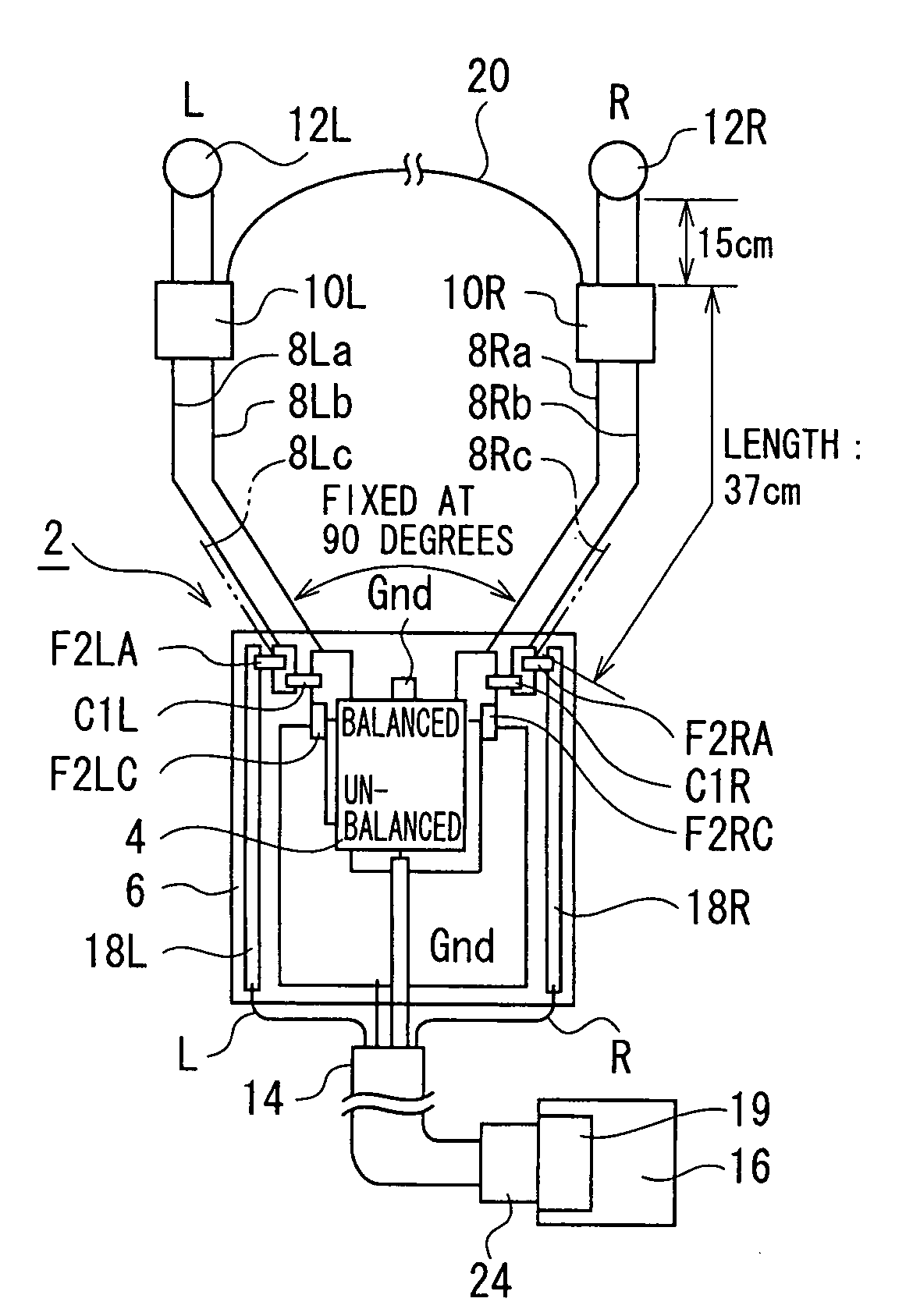
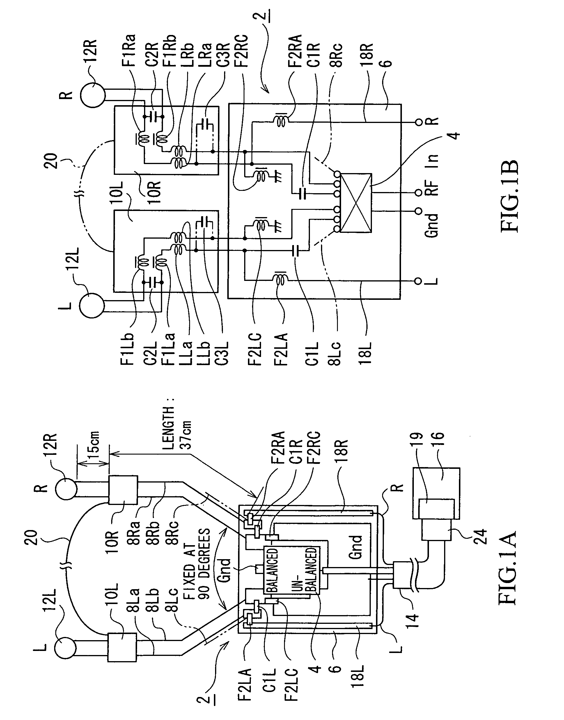
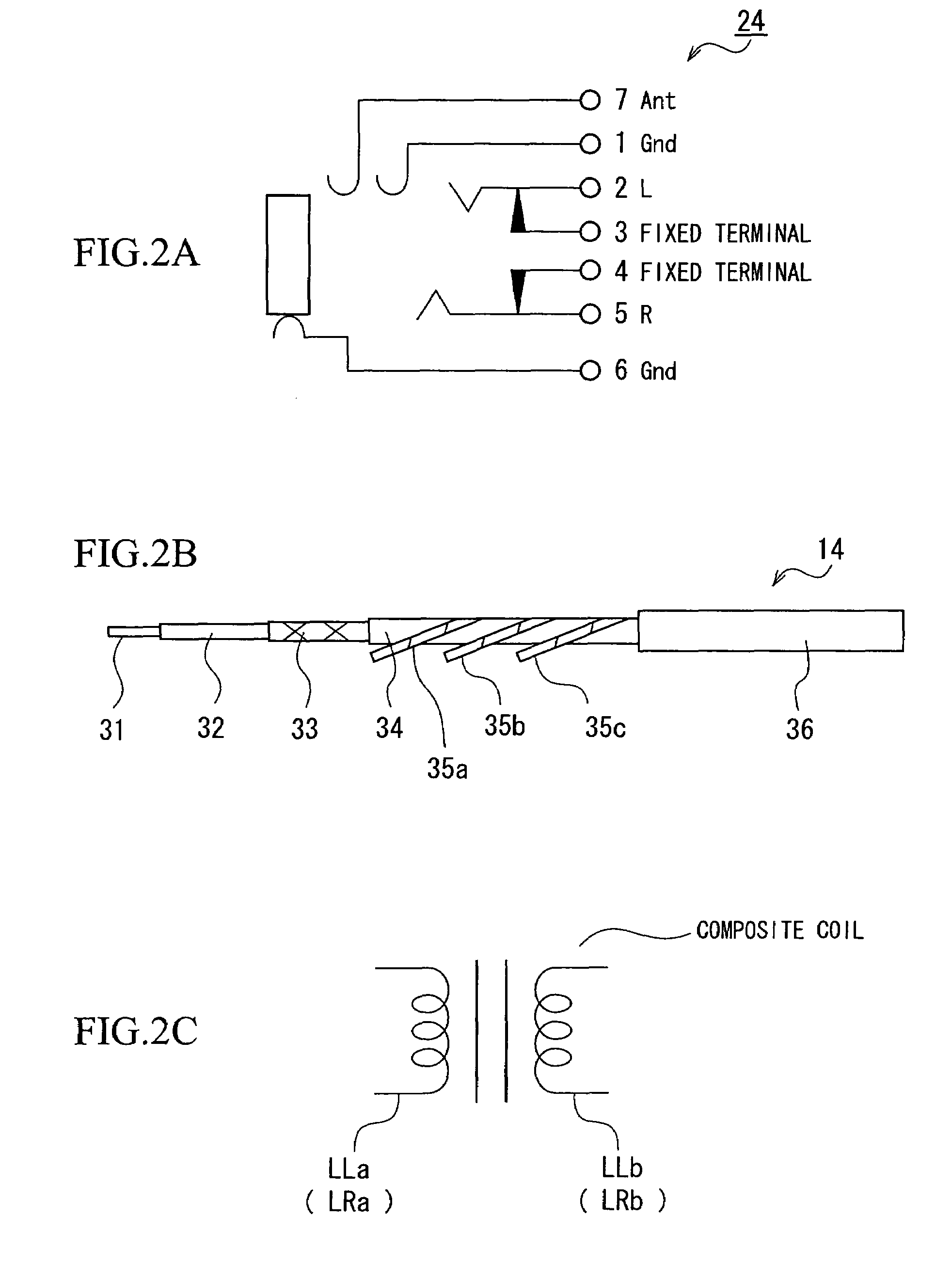
[0056]FIGS. 1A and 1B show a first embodiment of an earphone antenna of the present invention, in which FIG. 1A is a principle-illustrating configurational diagram, and FIG. 1B is an equivalent circuit diagram. FIGS. 2A to 2C show individual components for use in the earphone antenna, in which FIG. 2A is a diagram showing a pin-jack connector; FIG. 2B is a configurational diagram of a coaxial cable; and FIG. 2C is a configurational diagram of a composite coil.

[0057]In the drawings, reference symbol 2 denotes the present earphone antennal (the first embodiment of the earphone antenna of the present invention), which includes a matching box 6 for housing a balun 4 and the like, audio / high-frequency dual-function signal lines 8La, 8Lb, 8Ra, 8Rb as earphone cords connected to terminals on a balanced side of the above-mentioned balun 4, and a pair of loading boxes 10L, 10...


PUM


Abstract

An earphone antenna in which a balun is connected to one side and the other side having an audio / high-frequency dual-function signal connecting the earphone unit via a loading coil and wireless equipment connected to the balun, the loading coil selecting low impedance for fundamental frequency and selecting to obtain high impedance for higher frequencies, in order to integrate earphone and antenna.

Description

[0001]This application is a 371 of PCT / JP04 / 01485, filed Feb. 12, 2004.TECHNICAL FIELD[0002]The present invention relates to a so-called earphone antenna in which earphones are connected to wireless equipment for reproducing audio (emitting sound) and cords of which are used as an antenna. Particularly, the invention relates to an earphone antenna, a composite coil and a coaxial cable used for the earphone antenna, and a wireless device provided with the earphone antenna, which are capable of obtaining a high receiving sensitivity over a wide range of frequencies without performing a sensitivity adjusting operation or a receiving frequency switching operation, and which are not subject to a negative influence from the human body through the earphones.BACKGROUND ART[0003]As an antenna for a wireless device that receives high-frequency electrical waves, one using earphones themselves, one formed by arranging conductor lines within a housing of the wireless device, and the like have ty...

Claims


Application Information

Patent Timeline
Patent Type & Authority Patents(United States)
IPC IPC(8): H01Q1/12H01P5/10H01Q1/44H01Q1/24H01Q1/50H01Q9/16H04B1/38
CPCH01Q1/242H01Q1/273H01Q1/46H01Q9/16H04R1/1033H01Q1/44H01P5/10H01Q1/24
Inventor YOSHINO, YOSHITAKAOOZEKI, MINORUIMAGAWA, TOSHIYUKI
Owner SONY CORP
Why Eureka
Try Eureka