
Multi-mode envelope restoration architecture for RF transmitters

a transmitter and multi-mode technology, applied in the field of radiofrequency transmitters, can solve the problems of poor efficiency of switch-mode envelope modulation for use in wcdma (wideband code-division multiple access)

Inactive Publication Date: 2007-06-26
NOKIA CORP
View PDF6 Cites 54 Cited by
  • Summary
  • Abstract
  • Description
  • Claims
  • Application Information

AI Technical Summary

Benefits of technology

The solution enables efficient signal transmission across both GSM / EDGE and WCDMA modes by optimizing power control and reducing power losses, enhancing overall transmitter efficiency and dynamic range.

Problems solved by technology

However, the efficiency of switch-mode envelope modulation for use in WCDMA (Wideband Code-Division Multiple Access) is poor due to the high switching frequency needed to achieve required modulation bandwidth in WCDMA.

Method used


Image

  • Multi-mode envelope restoration architecture for RF transmitters
  • Multi-mode envelope restoration architecture for RF transmitters
  • Multi-mode envelope restoration architecture for RF transmitters

Examples


Embodiment Construction

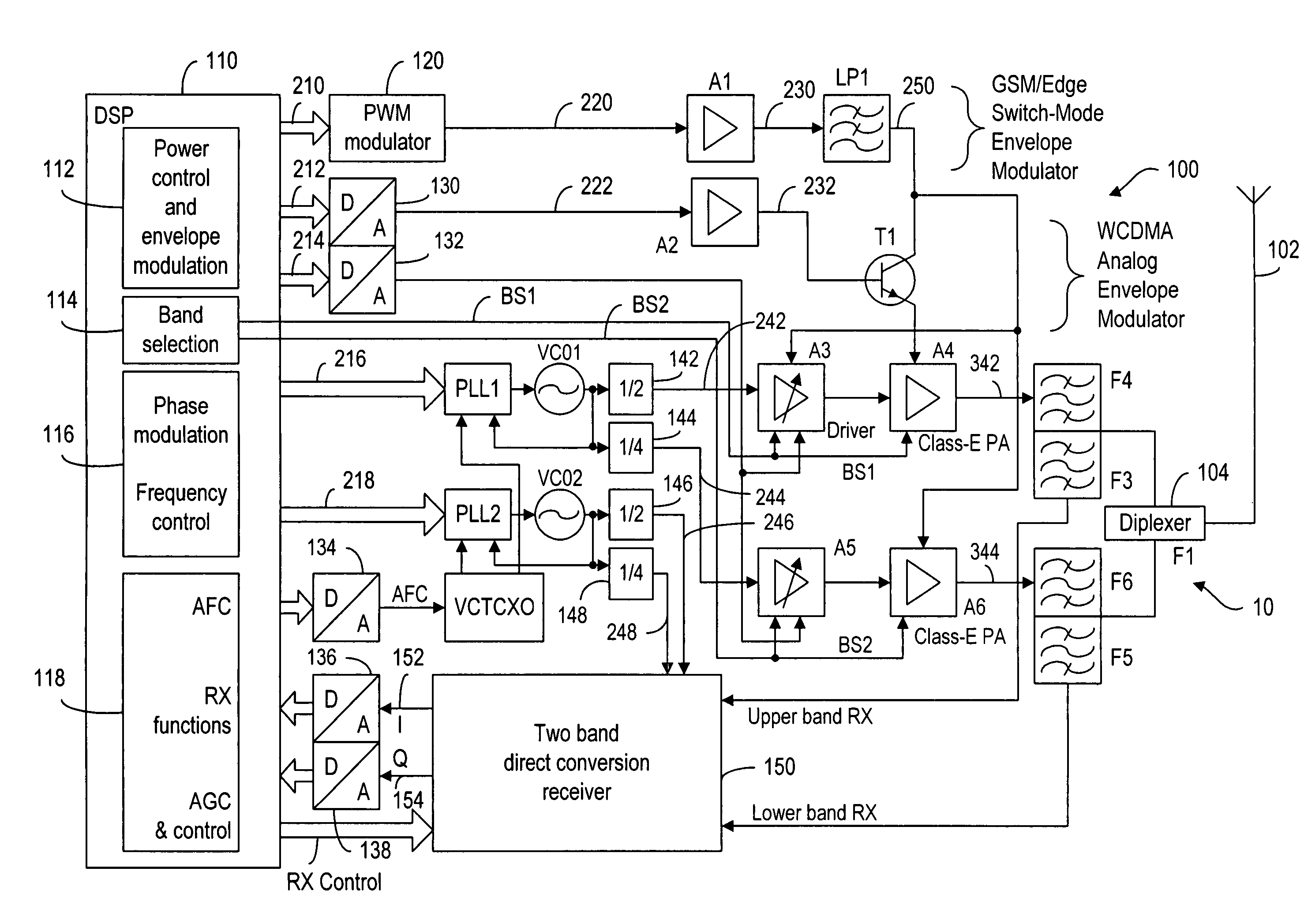
[0048]FIG. 3 shows a dual-band architecture for a multi-mode envelope restoration transceiver 10, which comprises a transmitter 100. The transceiver 10 has a common antenna 102 for transmitting signals and receiving signals. The common antenna 102 is split to two different frequency bands by a diplexer 104. Transmitter carrier signal is generated within a synthesizer PLL1 / VCO1. The output frequency of the synthesizer is divided by 2 by a frequency divider 142 for an upper band (approximately 1900 MHz) and by 4 by a frequency divider 144 for a lower band (approximately 900 MHz). The lower band can be used for a GSM (Global System for Mobile Communications) or EDGE (Enhanced Data Rates for GSM Evolution) mode, while the upper band can be used for a WCDMA mode, for example.

[0049]As in a prior art envelope restoration transmitter, the modulated signal is divided into an envelope baseband component and a phase modulated radio-frequency (PM RF) component. The PM component 216 is generated...


PUM


Abstract

An RF transceiver having dual-mode envelope restoration architecture. In narrow-band applications such as GSM / EDGE, a switch-mode amplifier is used to provide an envelope signal for amplitude modulating the phase-modulated signals. To achieve required modulation bandwidth in wide-band applications such as WDCMA, an analog amplifier is used to provide the envelope signal. Furthermore, in the wide-band mode, the envelope modulation is applied through the base of an emitter follower while the collector voltage is scaled to achieve a desired power output in the amplitude-modulated signals.

Description

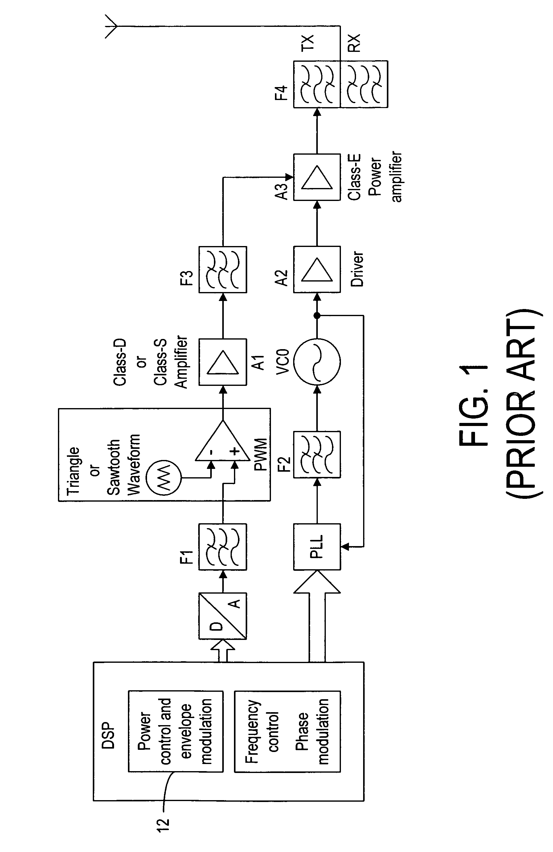
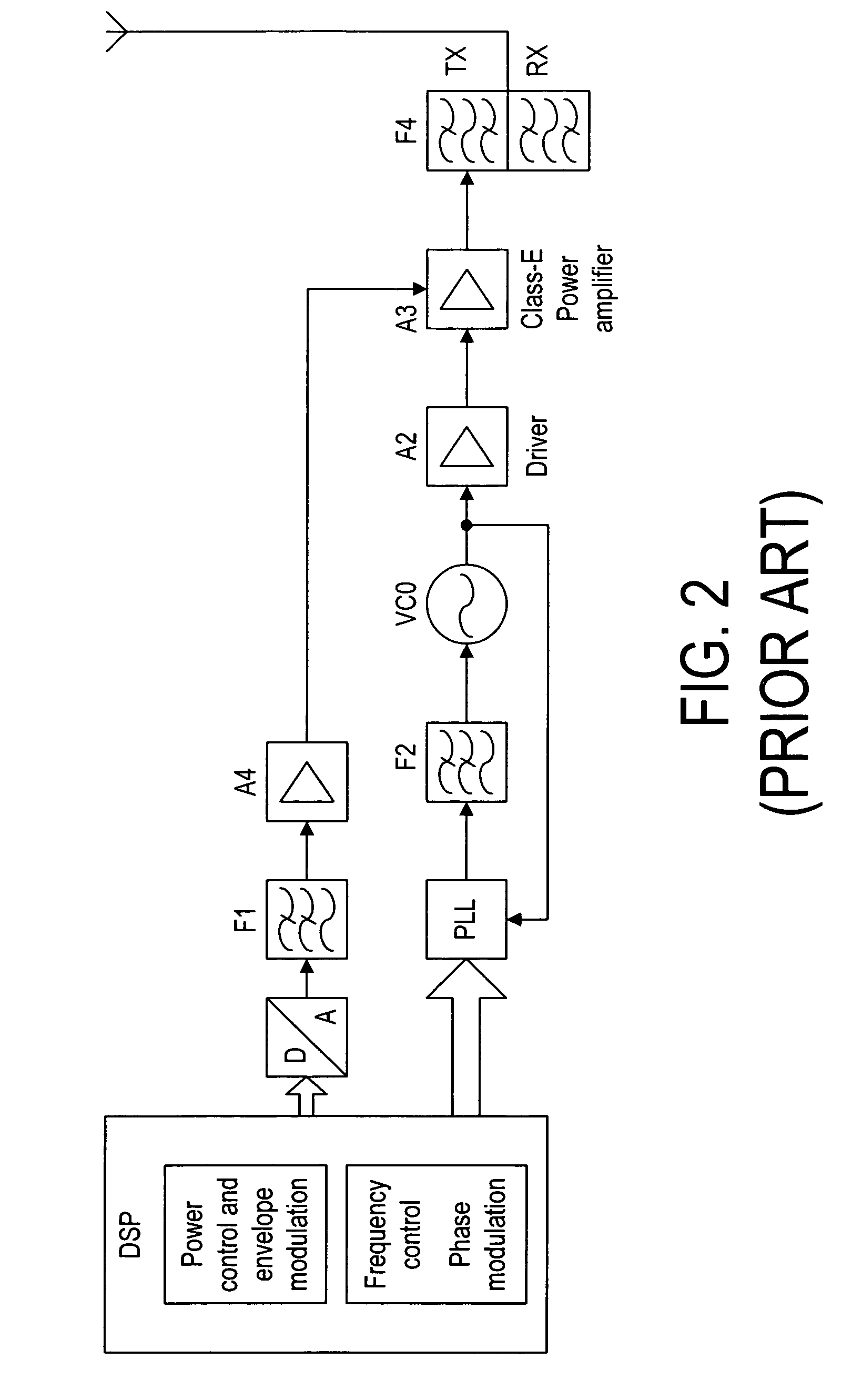
[0001]This is a continuation application of and claims priority to application Ser. No. 10 / 246,574 filed on Sep. 17, 2002 now U.S. Pat. No. 7,123,664.FIELD OF THE INVENTION[0002]The present invention is related generally to radio-frequency transmitters and, more specifically, to envelope restoration transmitters.BACKGROUND OF THE INVENTION[0003]Envelope elimination and restoration (EER) principle is known in the art. For example, Raab (U.S. Pat. No. 6,256,482 B1) discloses a power-conserving drive-modulation method for EER transmitter, wherein an envelope baseband component and a phase modulation (PM) radio-frequency (RF) component of a modulated signal are separately amplified and then combined in a signal for transmission. The major advantage of the EER transmitter is that the RF PM signal is amplified by highly efficient nonlinear RF amplifiers and the last RF amplifier is amplitude-modulated by the envelope signal, thereby restoring the modulation at the output of the transmitte...

Claims


Application Information

Patent Timeline
Patent Type & Authority Patents(United States)
IPC IPC(8): H04L27/04H03F3/38H04B1/40H04L27/00H04L27/36
CPCH04B1/406H04L27/0008H04L27/361H03F3/2176
Inventor MATERO, JORMA
Owner NOKIA CORP
Learn More