Composite hydroentangling nozzle strip and method for producing nonwoven fabrics therewith

a technology of nozzle strip and composite hydroentangling, which is applied in the direction of spray/projecting, lighting and heating apparatus, and drying machines with progressive movements, etc. it can solve the problems of ineffective entanglement of fibers, many design process constraints, and broken water jets that have practically no utility, so as to improve cohesion and appearance.

Inactive Publication Date: 2007-07-03
ADVANCED FLUID TECH INC +1
View PDF24 Cites 22 Cited by
  • Summary
  • Abstract
  • Description
  • Claims
  • Application Information

AI Technical Summary

Benefits of technology

[0010]One of the main hydroentangling nozzle properties that allow for a constricted water jet is a sharp inlet in order to promote the vena contracts effect at the moment the water enters the passage or capillary of the nozzle. Therefore, an important concern in the hydroentangling process is the effect of orifice erosion, which can render the nozzle strip ineffective after a relatively short period of time due to the lack of water jet constriction. FIGS. 6A and 6B depict pictures taken by a Burleigh Horizon non-contact green laser microscope of a typical hydroentangling nozzle strip in new condition and after use, respectively. FIG. 6A depicts a new nozzle shown having sharp inlets whereas FIG. 6B depicts a used nozzle with eroded edges. Eroded nozzles do not have sharp-edge inlets and once the inlet loses its sharpness, the orifice will no longer be capable of generating a constricted water jet.
[0012]If the above-mentioned cavitation cloud reaches the nozzle outlet before it disperses, downstream air comes into the nozzle, fills the cavity and cavitation stops in a phenomenon called hydraulic flip. Cavitation is desirable if it ends up with a hydraulic flip inside the nozzle due to the generation of a constricted waterjet with a long breakup length. However, intermediate levels of cavitation (cavitating flow) results in a rapid disintegration of the water jet as well as strong erosion inside the nozzle due to the collapse of cavitation bubbles close to the nozzle surface which generates a strong pressure wave and rapid deterioration of the nozzle surface.
[0030]Methods are also provided for producing nonwoven fabrics with the novel composite nozzle strips. The methods generally comprise providing a substrate comprising a material of a first hardness, the substrate having a plurality of apertures of a first diameter, and providing orifice elements (alone or in a positioning strip) further defining an aperture or providing an orifice strip having a plurality of apertures wherein the orifice elements or orifice strip comprise a material of a second hardness greater than the first hardness and further wherein the apertures defined in the orifice elements or orifice strip are of a second diameter less than the first diameter. The methods further comprise affixing the orifice elements or orifice strip to the substrate so that the apertures in the orifice elements or orifice strip are aligned with the plurality of apertures in the substrate, exposing the apertures of the orifice elements or orifice strip to pressurized water to form at least one water jet, guiding a fibrous web onto a supporting member beneath the at least one water jet, and subjecting the fibrous web to the at least one water jet and thereby providing enhanced cohesion and appearance modification to the fibrous web.

Problems solved by technology

Manufacturing thousands of such delicate tiny orifices next to each other places many constraints on the design process.
Broken water jets have practically no utility and consequently are not able to entangle fibers efficiently.
This gap filling forms an envelope around the water flow, which results in formation of a constricted water jet.

Method used


Image

  • Composite hydroentangling nozzle strip and method for producing nonwoven fabrics therewith
  • Composite hydroentangling nozzle strip and method for producing nonwoven fabrics therewith
  • Composite hydroentangling nozzle strip and method for producing nonwoven fabrics therewith

Examples


Embodiment Construction

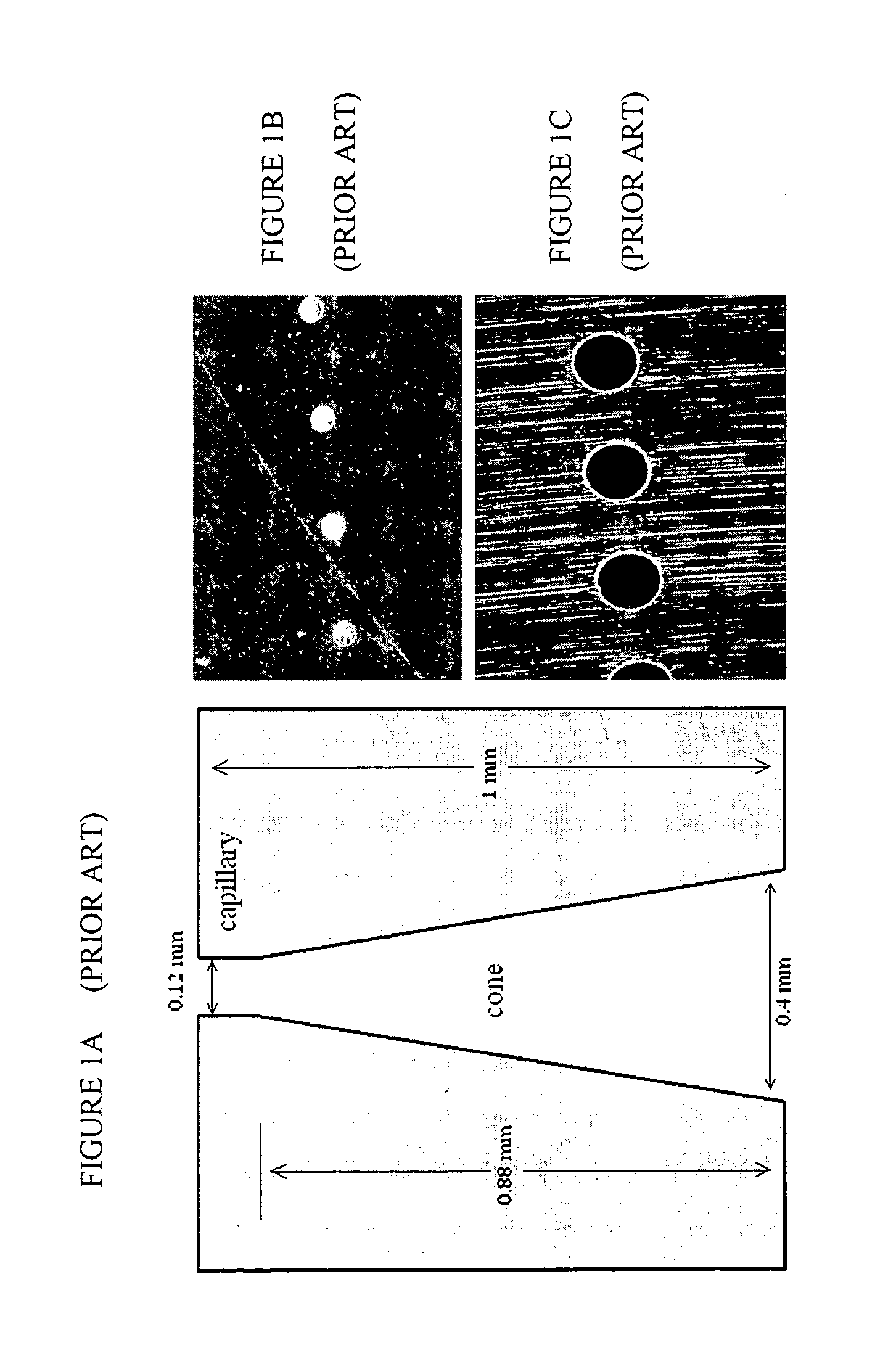
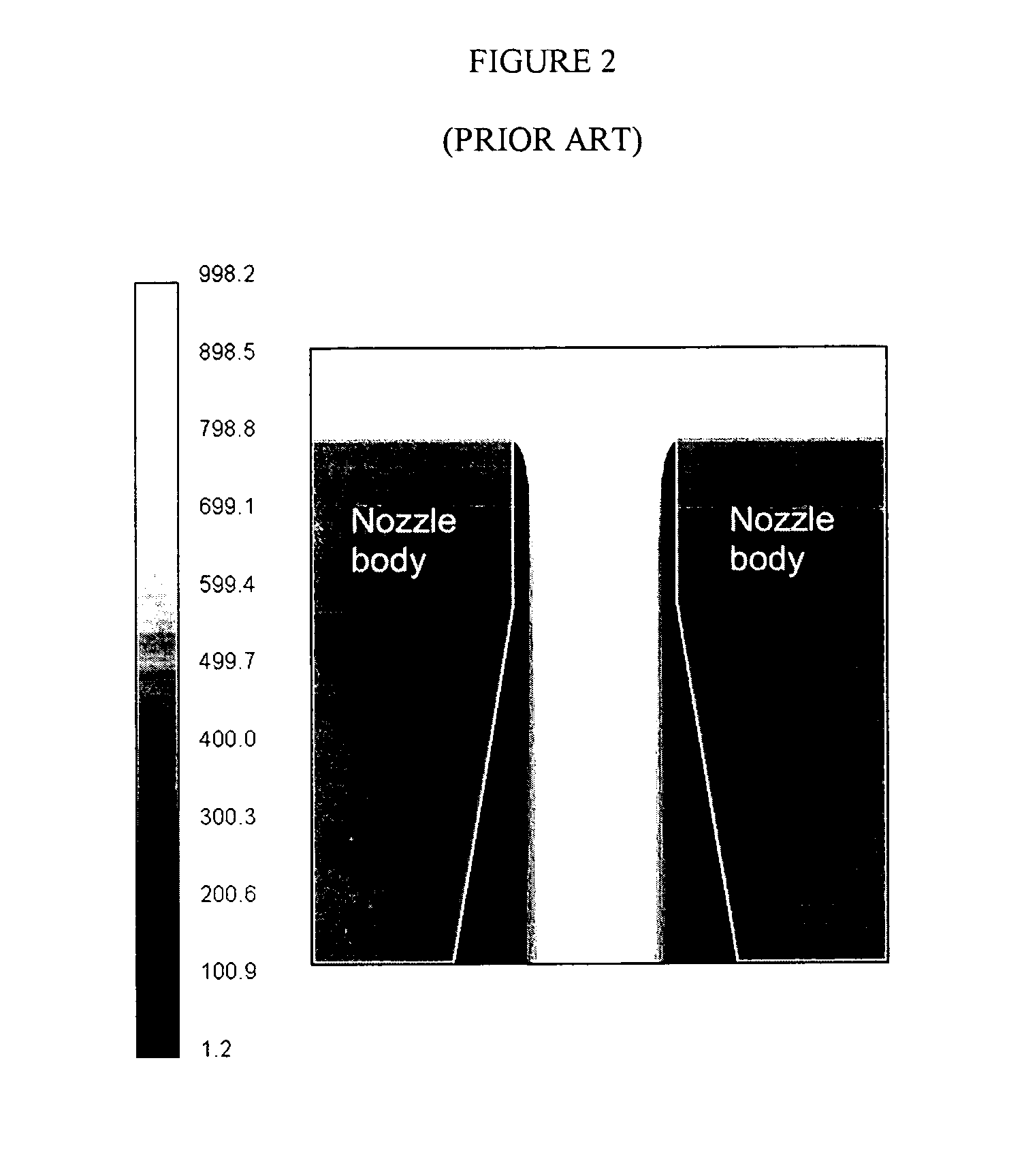
[0044]As discussed above, conventional hydroentangling nozzles made of stainless steel and other metals are known to undergo severe erosion in a relatively short period of time. At higher pressures, the nozzles tend to erode more rapidly, which leads to formation of a non-constricted water jet, or spray, which lowers the effectiveness of the hydroentangling process. Nozzles that fail due to erosion must be replaced, imposing a large replacement cost for the process and an undesirable stoppage in production line. Other prior art nozzles have incorporated other materials, such as sapphire, inside the nozzle assembly itself, but this has led to numerous production problems inherent with replacing inner parts of nozzle strip assemblies.

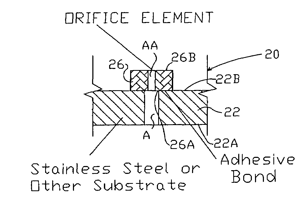
[0045]Applicants have discovered a novel composite hydroentangling nozzle strip which has a higher degree of erosion resistance than previous prior art nozzle strips. The improved composite nozzle strip comprises a substrate, such as non-corrosive stainle...


PUM

PropertyMeasurementUnit
aspect ratioaaaaaaaaaa
thicknessaaaaaaaaaa

Abstract

A composite nozzle strip for hydroentangling of a fibrous mass is provided to lower nozzle erosion potential and increase operational efficiency. The composite nozzle strip comprises a substrate comprising a material of a first hardness having at least one aperture and at least one orifice element comprising a material of a second hardness greater than the first hardness and further defining an aperture of a second diameter less than the first diameter. The at least one orifice element is affixed to the substrate so that the aperture in the orifice element is aligned with the at least one aperture in the substrate for creation of a constricted water jet when subjected to pressurized water.

Description

TECHNICAL FIELD[0001]The subject matter disclosed herein relates generally to apparatuses and methods for producing nonwoven fabrics through the hydroentangling process, and more particularly to providing a composite hydroentangling nozzle strip for mechanically bonding a fibrous mass.BACKGROUND ART[0002]Hydroentanglement or “spunlacing” is a process used for mechanically bonding a web of loose fibers to form fabrics directly from fibers. Fabrics formed by the hydroentanglement process typically belong to those in the nonwovens' family of engineered fabrics. The underlying mechanism in hydroentanglement is the subjecting of the fibers to a non-uniform pressure field created by a successive bank of high-velocity water jets. The impact of the water jets with the fibers, while they are in contact with their neighbors, displaces and rotates the fibers with respect to their neighbors and entangles the same with neighboring fibers. During these relative displacements, some of the fibers t...

Claims


Application Information

Patent Timeline
Patent Type & Authority Patents(United States)
IPC IPC(8): D04H1/46D06B1/02C03B37/10D04H1/70D04H3/10D04H5/08D04H11/08D04H18/00D06C23/00
CPCD04H1/465D04H18/00D04H1/492D04H18/04
Inventor DIXON, MICHAEL D.LOWDER, JAMES T.POURDEYHIMI, BEHNAMTAFRESHI, HOOMAN VAHEDI
Owner ADVANCED FLUID TECH INC
Why Eureka
Try Eureka