Compliant walled combustion devices

a combustion device and wall technology, applied in the direction of steam engine plants, cylinders, casings, etc., can solve the problems of increasing thermal dissipation, and achieve the effects of improving thermal management, reducing thickness, and increasing combustion efficiency and volume displacemen

Inactive Publication Date: 2007-07-03
SRI INTERNATIONAL
View PDF36 Cites 55 Cited by
  • Summary
  • Abstract
  • Description
  • Claims
  • Application Information

AI Technical Summary

Benefits of technology

[0009]Some compliant walls or segments stretch during combustion. The compliant segment may decrease in thickness during the stretch. Compliant segment thickness decreases often lead to a dynamic increase in combustion chamber volume. This raises maximum volume for a combustion chamber, which increases combustion efficiency and volume displacement for a given linear displacement.
[0010]Compliant segments and walls may also dynamically vary surface area of the combustion chamber, which improves thermal management. During and after combustion, compliant walls may increase their surface area and provide a greater area for conductive heat transfer out of the chamber. When a compliant wall thins, the conductive heat transfer path through the wall also shortens, which further increases thermal dissipation.
[0013]In another aspect, the present invention relates to a combustion device for producing mechanical energy from a fuel. The combustion device comprises a constraint that reduces deformation of a portion of a compliant segment during combustion.

Problems solved by technology

When a compliant wall thins, the conductive heat transfer path through the wall also shortens, which further increases thermal dissipation.

Method used


Image

  • Compliant walled combustion devices
  • Compliant walled combustion devices
  • Compliant walled combustion devices

Examples


Embodiment Construction

[0055]The present invention is described in detail with reference to a few preferred embodiments as illustrated in the accompanying drawings. In the following description, numerous specific details are set forth in order to provide a thorough understanding of the present invention. It will be apparent, however, to one skilled in the art, that the present invention may be practiced without some or all of these specific details. In other instances, well known process steps and / or structures have not been described in detail in order to not unnecessarily obscure the present invention.

Overview

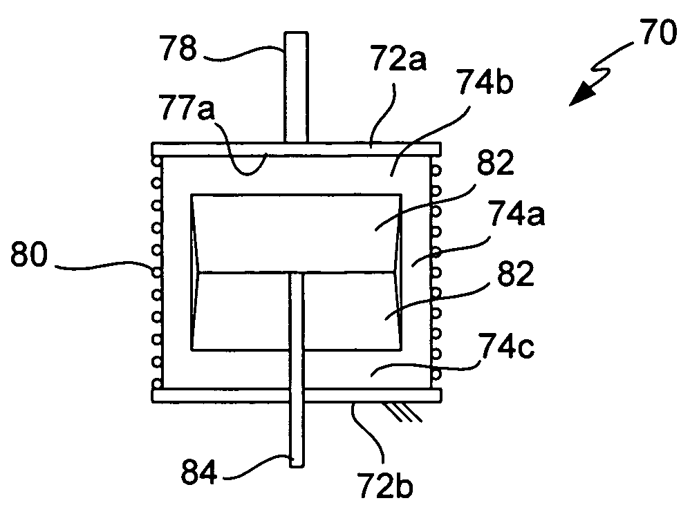
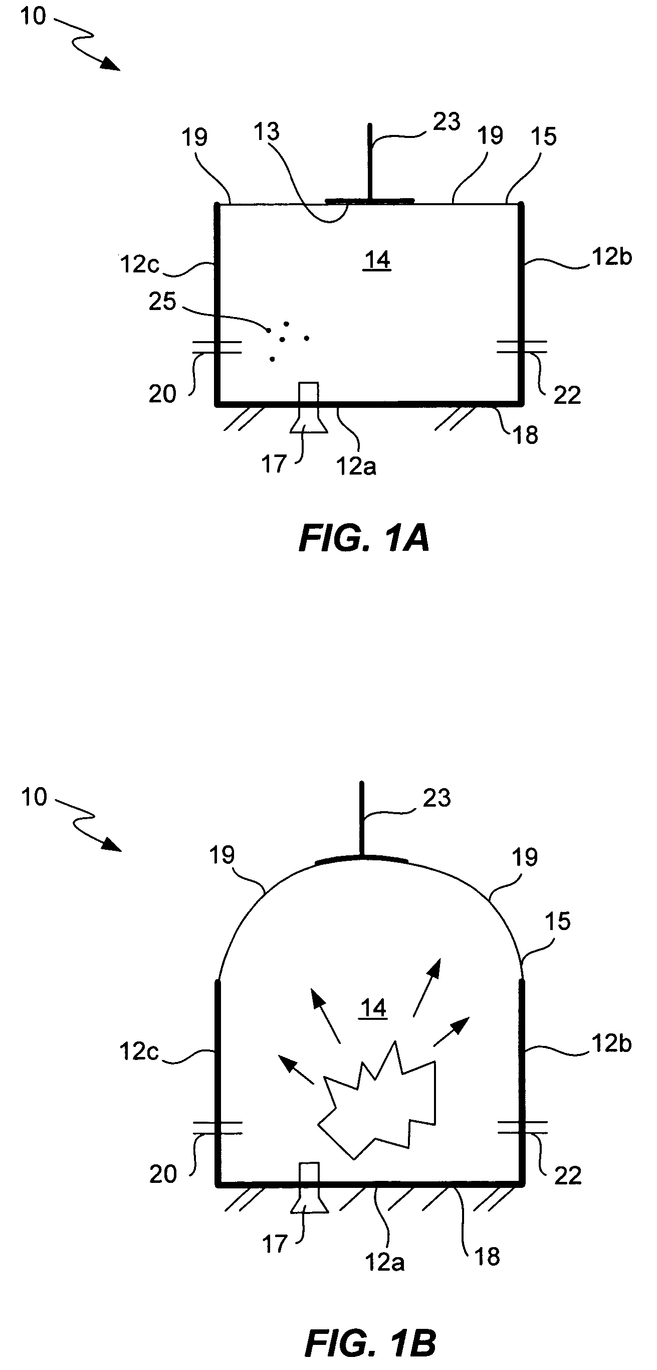
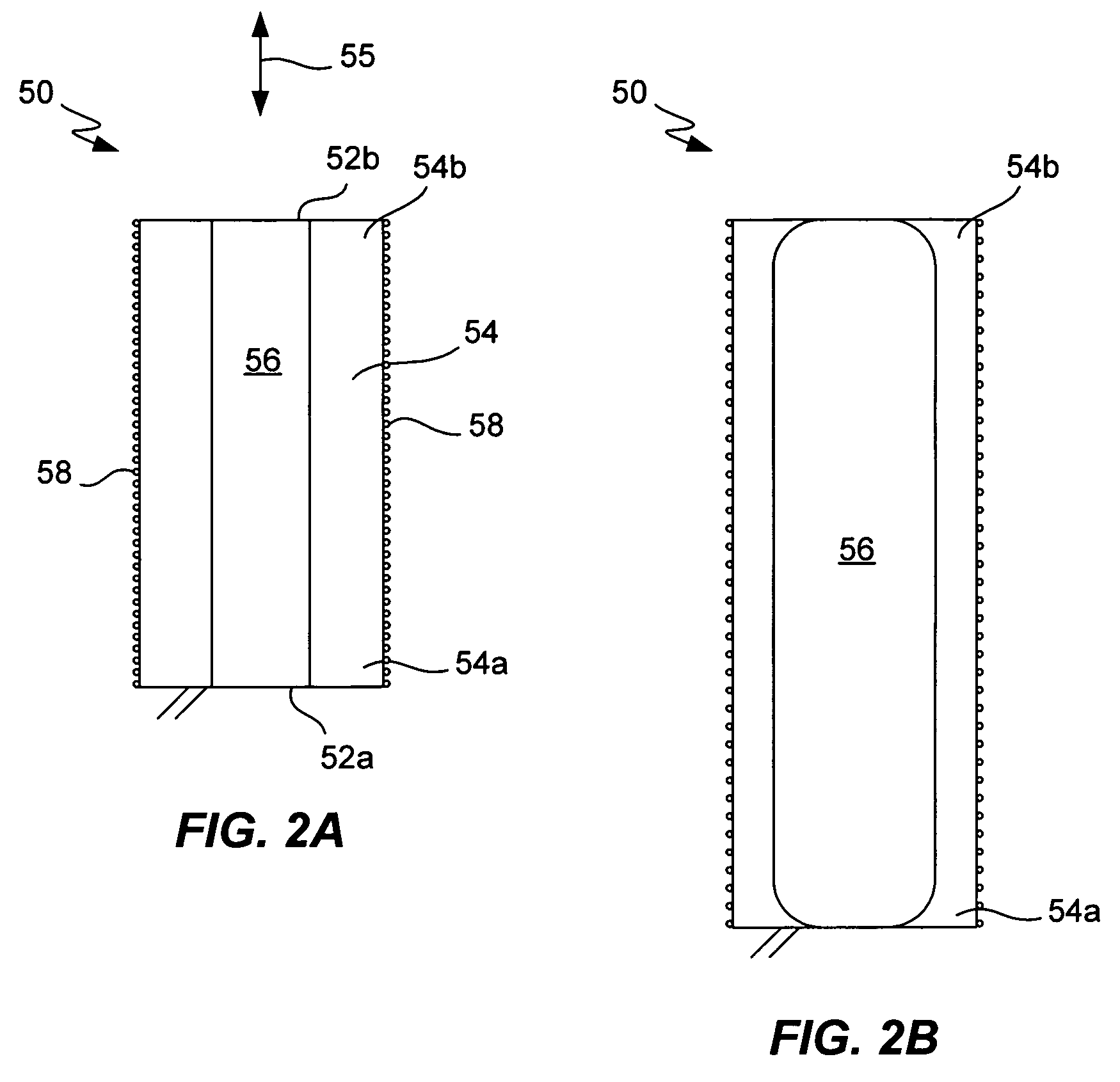
[0056]Combustion refers to a rapid chemical change that produces mechanical energy. The chemical change usually burns a fuel to produce heated gases and pressure resulting from expansion of the heated gases. Combustion thus allows a small amount of fuel, when ignited in a combustion chamber, to produce mechanical energy in the form of an expanding gas.

[0057]Combustion devices of the present inventi...


PUM


Abstract

Combustion devices described herein comprise a compliant combustion chamber wall or segment. The compliant segment deforms during combustion in the combustion chamber. Some devices may include a compliant wall configured to stretch responsive to pressure generated by combustion of a fuel in the combustion chamber. A coupling portion translates deformation of the compliant segment or wall into mechanical output. One or more ports are configured to inlet an oxygen source and fuel into the combustion chamber and to outlet exhaust gases from the combustion chamber.

Description

CROSS-REFERENCE TO RELATED APPLICATION[0001]This application claims priority under 35 U.S.C. §119(e) from commonly owned and U.S. Provisional Patent Application No. 60 / 574,891 filed May 26, 2004, naming R. Pelrine et al. as inventors, and titled “Polymer Engines For Lightweight Portable Power”, which is incorporated by reference herein in its entirety for all purposes; this application also claims priority under 35 U.S.C. §119(e) from commonly owned and U.S. Provisional Patent Application No. 60 / 608,741 filed Sep. 9, 2004, which is also incorporated by reference herein in its entirety for all purposes.U.S. GOVERNMENT RIGHTS[0002]This invention was funded in part with Government support under contract number DAAD19-03C-0067 awarded by the United States Army. The Government has certain rights in this invention.FIELD OF THE INVENTION[0003]The present invention relates generally to combustion devices that convert chemical energy stored in a fuel to mechanical energy. More particularly, ...

Claims


Application Information

Patent Timeline
Patent Type & Authority Patents(United States)
IPC IPC(8): F02B75/22F02F3/00
CPCF02B75/36
Inventor PELRINE, RONALD E.STANFORD, SCOTT E.PRAHLAD, HARSHAOH, SEAJINHEIM, JON
Owner SRI INTERNATIONAL
Why Eureka
Try Eureka