Interbody fusion device and method for restoration of normal spinal anatomy

a fusion device and spinal column technology, applied in the direction of internal osteosynthesis, osteosynthesis devices, prosthesis, etc., can solve the problems of inconvenient surgical procedures, inconvenient fusion, and inability to maintain the stability of the segment, etc., to achieve the effect of restoring normal spinal anatomy, avoiding the need for a rod or plate to stabilize the level during fusion, and avoiding the need for a rod or plate to be implanted

Inactive Publication Date: 2007-07-03
WARSAW ORTHOPEDIC INC
View PDF159 Cites 148 Cited by
  • Summary
  • Abstract
  • Description
  • Claims
  • Application Information

AI Technical Summary

Benefits of technology

[0006]Interbody fusion devices can be generally divided into two basic categories, namely solid implants and implants that are designed to permit bone ingrowth Solid implants are represented by U.S. Pat. Nos. 4,878,915; 4,743,256; 4,349,921 and 4,714,469. The remaining patents discussed above include some aspect that permits bone to grow across the implant. It has been found that devices that promote natural bone ingrowth achieve a more rapid and stable arthrodesis. The device depicted in the Michelson patent is representative of this type of hollow implant which is typically filled with autologous bone prior to insertion into the intra-discal space. This implant includes a plurality of circular apertures which communicate with the hollow interior of the implant, thereby providing a path for tissue growth between the vertebral end plates and the bone or bone substitute within the implant. In preparing the intra-discal space, the end plates are preferably reduced to bleeding bone to facilitate this tissue ingrowth. During fusion, the metal structure provided by the Michelson implant helps maintain the patency and stability of the motion segment to be fused. In addition, once arthrodesis occurs, the implant itself serves as a sort of anchor for the solid bony mass.
[0017]In another inventive method, the insertion site is prepared posteriorly, namely the disc space is dilated and a minor diameter hole is drilled into the vertebral end plates. A sleeve is also arranged to provide a working channel for the drilling and insertion steps. The fusion device is inserted into the drilled hole with the flat side walls facing the adjacent vertebra. The device is then rotated so that the external threads on the cylindrical portion cut into and engage the adjacent vertebrae. In addition, since the fusion device is tapered, the tapered outer surface of the device will angularly separate the adjacent vertebrae to restore the normal anatomic lordosis.

Problems solved by technology

Since the damaged disc material has been removed, something must be positioned within the intra-discal space, otherwise the space may collapse resulting in damage to the nerves extending along the spinal column.
With this technique once fusion occurred the hardware used to maintain the stability of the segment became superfluous.
Moreover, the surgical procedures necessary to implant a rod or plate to stabilize the level during fusion were frequently lengthy and involved.
A number of difficulties still remain with the many interbody fusion devices currently available.
While it is recognized that hollow implants that permit bone ingrowth into bone or bone substitute within the implant is an optimum technique for achieving fusion, most of the prior art devices have difficulty in achieving this fusion, at least without the aid of some additional stabilizing device, such as a rod or plate.
Moreover, some of these devices are not structurally strong enough to support the heavy loads and bending moments applied at the most frequently fused vertebral levels, namely those in the lower lumbar spine.
In other words, if the ingrowth openings are improperly sized or configured, the autologous bone will not endure the loading that is typically found to be necessary to ensure rapid and complete fusion.
In this instance, the bone impacted within the implant may resorb or evolve into simply fibrous tissue, rather than a bony fusion mass, which leads to a generally unstable construction.
On the other hand, the bone ingrowth openings must not be so extensive that the cage provides insufficient support to avoid subsidence into the adjacent vertebrae.
Another problem that is not addressed by the above prior devices concerns maintaining or restoring the normal anatomy of the fused spinal segment.
With the prior devices, the need to restore this curvature is neglected.
However, this over-reaming of the posterior portion is generally not well accepted because of the removal of load bearing bone of the vertebrae, and because it is typically difficult to ream through the posterior portion of the lower lumbar segment where the lordosis is greatest.
In most cases using implants of this type, no effort is made to restore the lordotic curvature, so that the cylindrical implant is likely to cause a kyphotic deformity as the vertebra settles around the implant.
This phenomenon can often lead to revision surgeries because the spine becomes imbalanced.

Method used


Image

  • Interbody fusion device and method for restoration of normal spinal anatomy
  • Interbody fusion device and method for restoration of normal spinal anatomy
  • Interbody fusion device and method for restoration of normal spinal anatomy

Examples


Embodiment Construction

[0033]For the purposes of promoting an understanding of the principles of the invention, reference will now be made to the embodiments illustrated in the drawings and specific language will be used to describe the same. It will nevertheless be understood that no limitation of the scope of the invention is thereby intended, such alterations and further modifications in the illustrated device, and such further applications of the principles of the invention as illustrated therein being contemplated as would normally occur to one skilled in the art to which the invention relates.

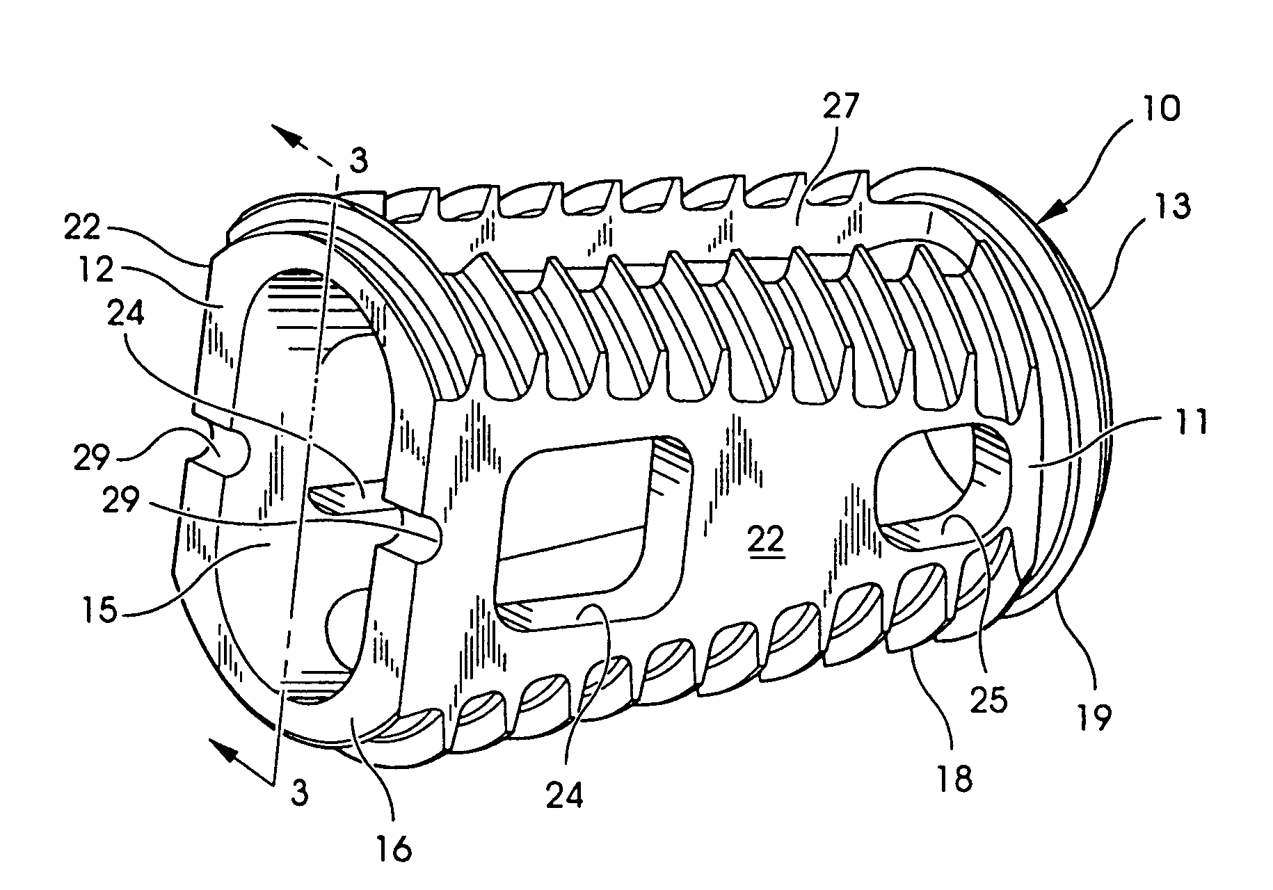
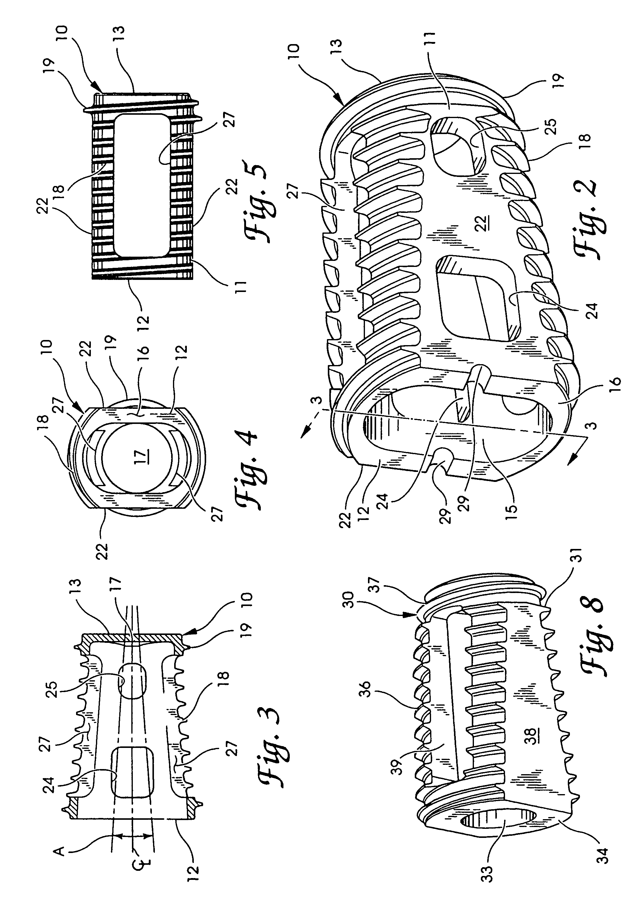
[0034]An interbody fusion device 10 in accordance with one aspect of the present invention is shown in FIGS. 2-5. The device is formed by a solid conical body 11, that is preferably formed of a biocompatible or inert material. For example, the body 11 can be made of a medical grade stainless steel or titanium, or other suitable material having adequate strength characteristics set forth herein. The device may a...


PUM

PropertyMeasurementUnit
heightaaaaaaaaaa
diameteraaaaaaaaaa
angleaaaaaaaaaa

Abstract

An interbody fusion device in one embodiment includes a tapered body defining a hollow interior for receiving bone graft or bone substitute material. The body defines exterior threads which are interrupted over portions of the outer surface of the device. The fusion device defines truncated side walls so that on end view the body takes on a cylindrical form. The side walls are provided with vascularization openings, and the body wall device includes opposite bone ingrowth slots extending through the interrupted thread portion of the body. In another embodiment, the tapered body is solid and formed of a porous biocompatible material having sufficient structural integrity to maintain the intradiscal space and normal curvature. The material is preferably a porous tantalum having fully interconnected pores to facilitate complete bone tissue ingrowth into the implant. An implant driver is provided which engages the truncated side walls to complete the cylindrical form of the implant at the root diameter of the interrupted threads, to thereby facilitate threaded insertion of the implant to the intra-discal space between adjacent vertebrae. Methods for posterior and anterior insertion of the fusion device are also disclosed.

Description

BACKGROUND OF THE INVENTION[0001]This application is a continuation of U.S. patent application Ser. No. 09 / 518,981, filed Mar. 3, 2000 now U.S. Pat. No. 6,645,206, which is a continuation of U.S. patent application Ser. No. 09 / 489,317, filed Jan. 21, 2000, now U.S. Pat. No. 6,375,655, issued Apr. 23, 2002, which is a continuation of U.S. patent application Ser. No. 09 / 209,602, filed Dec. 11, 1998, now abandoned, which is a continuation of U.S. patent application Ser. No. 09 / 157,735, filed Sep. 21, 1998, now abandoned, which is a continuation of U.S. patent application Ser. No. 09 / 111,197, filed Jul. 7, 1998, now abandoned, which is a continuation of U.S. patent application Ser. No. 08 / 882,611, filed Jun. 25, 1997, now abandoned, which is a continuation of U.S. patent application Ser. No. 08 / 835,306, filed Apr. 7, 1997, now abandoned, which is a continuation of U.S. patent application Ser. No. 08 / 413,353, filed Mar. 30, 1995, now U.S. Pat. No. 5,669,909, issued Sep. 23, 1997, which i...

Claims


Application Information

Patent Timeline
Patent Type & Authority Patents(United States)
IPC IPC(8): A61B17/58A61F2/44A61B17/56A61B17/16A61B17/70A61B17/88A61FA61F2/00A61F2/28A61F2/30A61F2/46A61L27/00A61L27/22A61L31/04
CPCA61B17/1671A61L31/047A61F2/4455A61F2/446A61F2/4611A61F2/4637A61L27/227A61B17/8891A61F2/30744A61F2/30767A61F2/442A61F2002/2835A61F2002/30136A61F2002/30143A61F2002/30153A61F2002/30158A61F2002/3021A61F2002/30217A61F2002/30504A61F2002/30774A61F2002/30777A61F2002/30785A61F2002/3082A61F2002/3085A61F2002/30858A61F2002/30874A61F2002/4475A61F2002/448A61F2002/464A61F2002/4641A61F2220/0025A61F2230/0004A61F2230/0017A61F2230/0019A61F2230/0026A61F2230/0067A61F2310/00017A61F2310/00023A61F2310/00095A61F2310/00131A61F2310/00161A61F2310/00179A61F2310/00796A61B17/8883A61L2430/38A61F2002/305A61F2002/30873A61F2002/30593
Inventor ZDEBLICK, THOMASRAY, III, EDDIEBOYD, LAWRENCE M.
Owner WARSAW ORTHOPEDIC INC
Why Eureka
Try Eureka