Structural element with rib-receiving member

a technology of ribs and components, applied in the field of structural elements, can solve the problems of high cost of use of honeycomb materials, high maintenance and repair costs, and high cost of life cycle, and achieve the effects of reducing the number of parts, and eliminating extensive assembly tooling

Inactive Publication Date: 2007-07-03
ROHR INC
View PDF18 Cites 30 Cited by
  • Summary
  • Abstract
  • Description
  • Claims
  • Application Information

AI Technical Summary

Benefits of technology

[0049]The structural element of the present invention permits the elimination of extensive assembly tooling and reduced part count. The structural element of the present invention also provides high strength, low weight, and improved stiffness.
[0050]Unlike honeycomb structures, the structure of this invention does not comprise small cellular areas that can trap moisture. In fact, the structure lends itself to direct venting and drainage systems to eliminate the accumulation of moisture. In addition, the structure does not have dissimilar metallic materials in the construction that can lead to galvanic corrosion.
[0051]The structure's durability is also enhanced by several features. The bonded joint is loaded in double shear and hence reduces any tendency for peel stresses. The rib-receiving member (also known as a “build-up”) provides a reinforced area for receiving any impact loads directly imparted to the rib member.

Problems solved by technology

Depending on the particular application, the use of such honeycomb material may be expensive, in terms of life cycle costs, and may require extensive maintenance and repair.
In some circumstances, it is also not readily adaptable to the attachment of other components.
This drawback may be overcome by reinforcing elements within the honeycomb, but this typically involves adding to the weight of the structural element and thus reducing the advantage of the low weight of the honeycomb material.
Furthermore, honeycomb core structures suffer from susceptibility to moisture intrusion resulting from their open-cell construction.
Even non-visible face sheet damage can create a path for moisture intrusion.
Repeated freeze / thaw cycles are also known to cause corrosion of aluminum honeycomb cores, and delamination of the face sheet from the core.
Repair complications due to honeycomb core water intrusion represent an additional difficulty.
Other problems with honeycomb core structures are the presence of undetected damage, cracked skins, poor radar transparency due to the metal foil and poor thermal insulation due to the conductivity of aluminum foil which is often a component of honeycomb structures.

Method used


Image

  • Structural element with rib-receiving member
  • Structural element with rib-receiving member
  • Structural element with rib-receiving member

Examples


Embodiment Construction

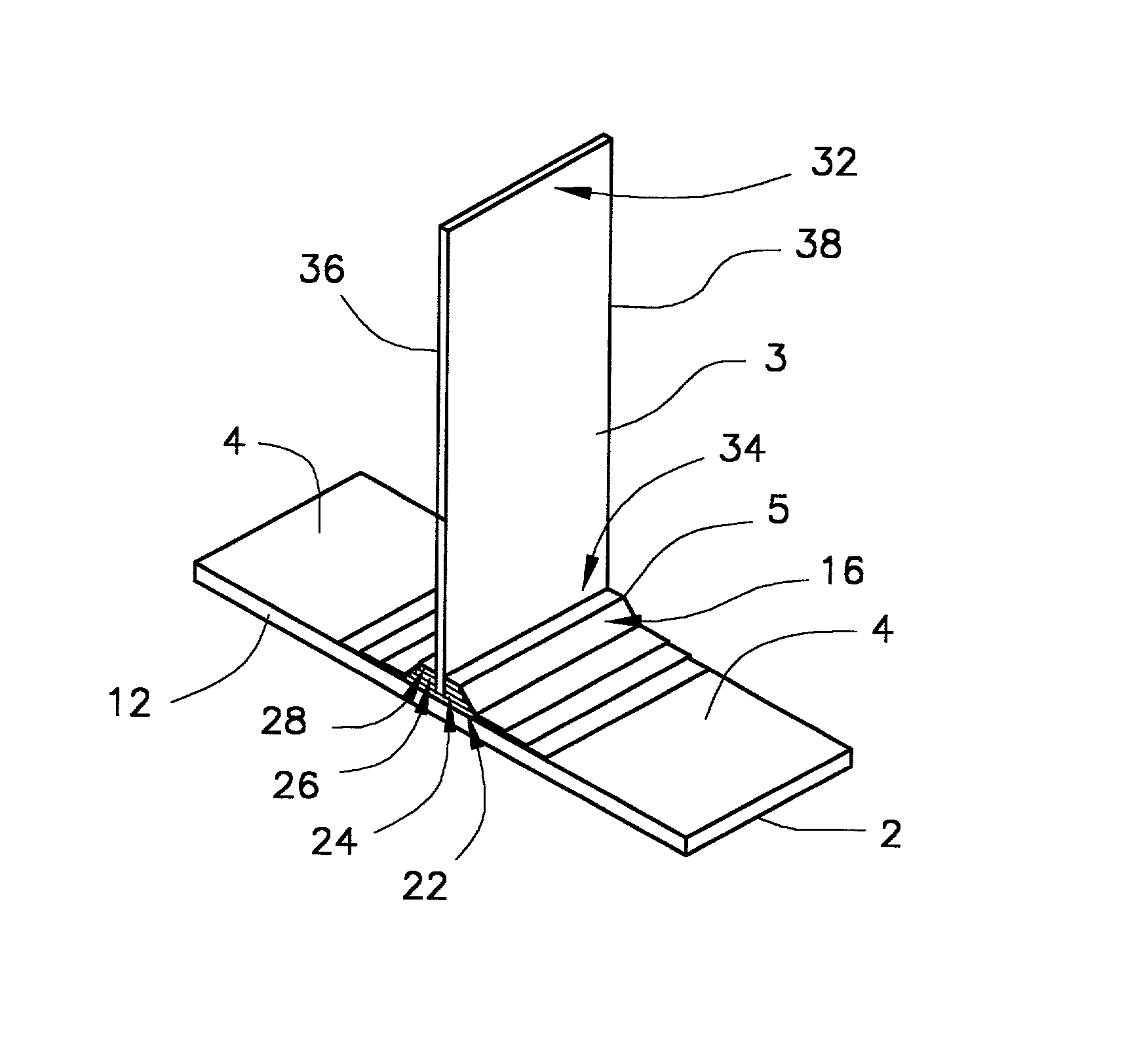
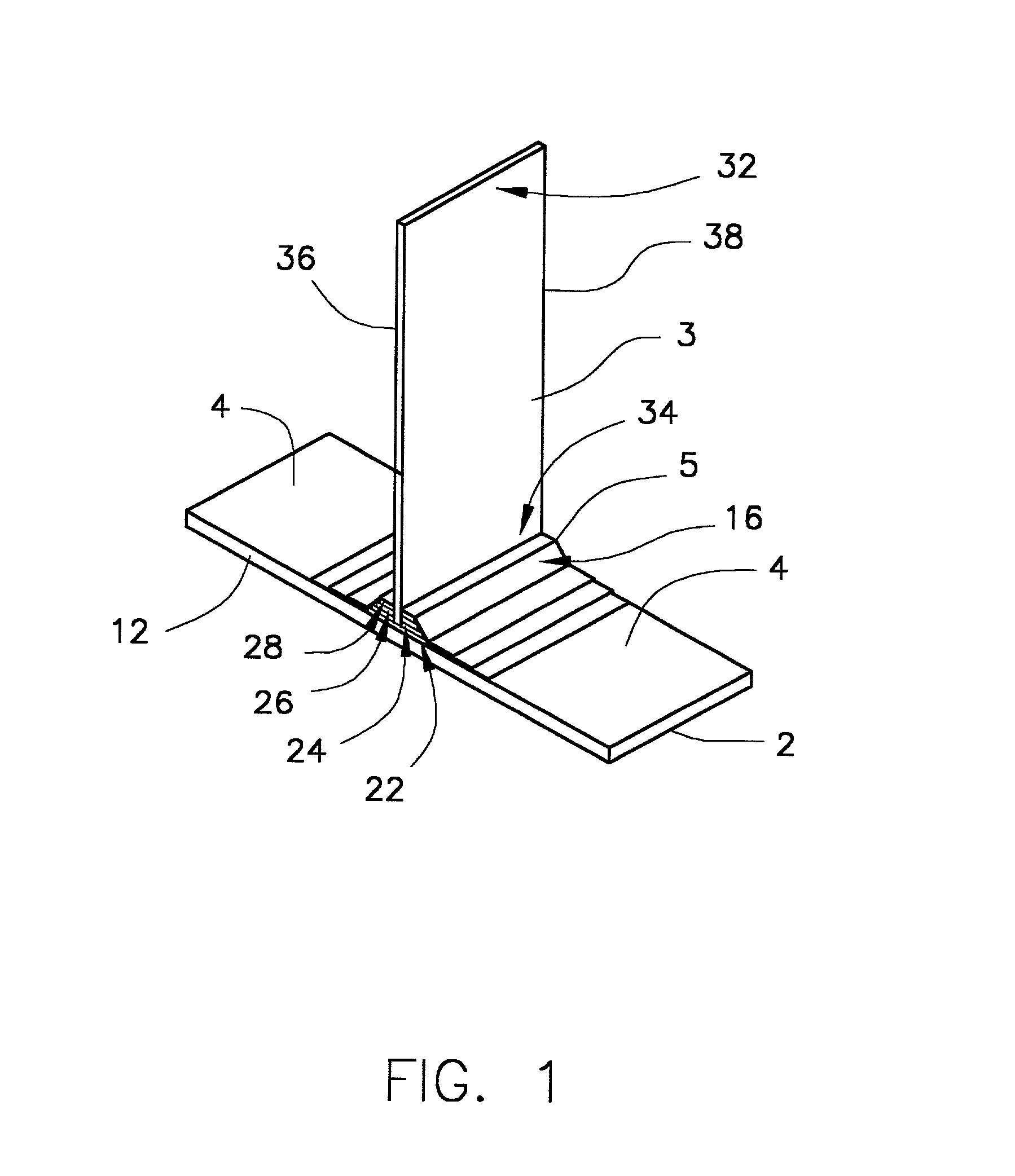
[0057]Various embodiments of this invention are illustrated by reference to FIGS. 1-4 herein. FIG. 1 shows the assembled structural element of this invention, which comprises: a first member or face sheet 12 having an inner surface 4 and an outer surface 2; a rib-receiving member 5; and a rib member 3 having a first end 34, a second end 32, a first edge 36 and a second edge 38. The first member may be, for example, a face sheet which is employed in an aerospace structure such as an aircraft wing or an internal aerospace structure such as a strut or the like. The first member may be fabricated from metal or a composite material, but is preferably fabricated from a composite material, as is further described herein. A second member (not shown) which is similar to the first member may receive second end 32 of rib member 3 using a second rib-receiving member, as shown, for example, in FIGS. 4A and 4B. Rib-receiving member 5 comprises at least one cover sheet 16 which has an engagement o...


PUM

PropertyMeasurementUnit
pressureaaaaaaaaaa
temperaturesaaaaaaaaaa
pressuresaaaaaaaaaa

Abstract

A structural element for use in aerospace applications such as a structural element suitable as an aircraft component is described. The composite structure comprises: (a) a rib having a first end and a second end; (b) at least one member such as a face sheet having an inner surface and an outer surface; and (c) a rib-receiving member integral to the inner surface of the at least one member, wherein the rib-receiving member comprises at least one rib-receiving element having an opening therein for receiving the first end of the rib and at least one cover sheet having an opening therein for receiving the first end of the rib.

Description

STATEMENT REGARDING FEDERALLY SPONSORED RESEARCH OR DEVELOPMENT[0001]The U.S. Government has a paid-up license in this invention and the right in limited circumstances to require the patent owner to license others on reasonable terms as provided for by the terms of Contract No. F33615-97-C-3212 awarded by the Department of the Air Force.BACKGROUND OF THE INVENTION[0002]1. Field of the Invention[0003]This invention relates to a structural element useful in aerospace applications, as well as a method of preparing such a structural element for use in aerospace applications, such as a structural element suitable as an aircraft component. In particular, in the present invention the structural element comprises a first member such as a face sheet, and at least one rib-receiving member integral to the first member, wherein the rib-receiving member comprises at least one rib-receiving element for receiving the rib member.[0004]2. Background Information[0005]Aircraft components including int...

Claims


Application Information

Patent Timeline
Patent Type & Authority Patents(United States)
IPC IPC(8): B32B3/00B29C65/00
CPCB29C66/43441B29C66/721B29C66/12441Y10T428/19Y10T428/17Y10T428/24479Y10T428/24322Y10T428/24174Y10T428/24289Y10T428/24537Y10T428/24182Y10T428/2457B29C65/00B29C65/02B29C65/4835B29C66/71B29C66/7212B29K2307/04B29K2063/00
Inventor PETERSON, DAVID A.MEANEY, JOHN E.
Owner ROHR INC
Why Eureka
Try Eureka