Microphone having a flexible printed circuit board for mounting components

Active Publication Date: 2007-07-03
SONION NEDERLAND
View PDF39 Cites 106 Cited by
  • Summary
  • Abstract
  • Description
  • Claims
  • Application Information

AI Technical Summary

Benefits of technology

[0008]The present invention solves the aforementioned problems. In one embodiment, the present invention involves a novel method and structure in which a flexible printed circuit board (“flex-print”) serves two functions: separating the diaphragm and backplate, and electrically connecting the cartridge and the buffer amplifier. Thus, the flex-print includes a spacer portion that maintains the appropriate distance between the diaphragm and the backplate

Problems solved by technology

In addition to the size of the microphone becoming smaller, the amount of electronic equipment fitted with a microphone is rapidly growing.
An incoming sound wave causes the diaphragm to move relative to the backplate, resulting in a capacitance change.
Be

Method used


Image

  • Microphone having a flexible printed circuit board for mounting components
  • Microphone having a flexible printed circuit board for mounting components
  • Microphone having a flexible printed circuit board for mounting components

Examples


Embodiment Construction

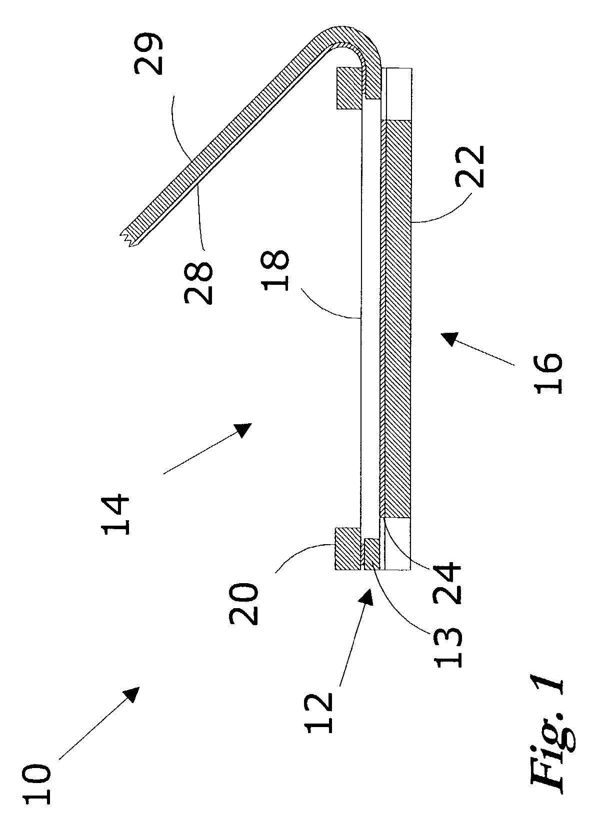
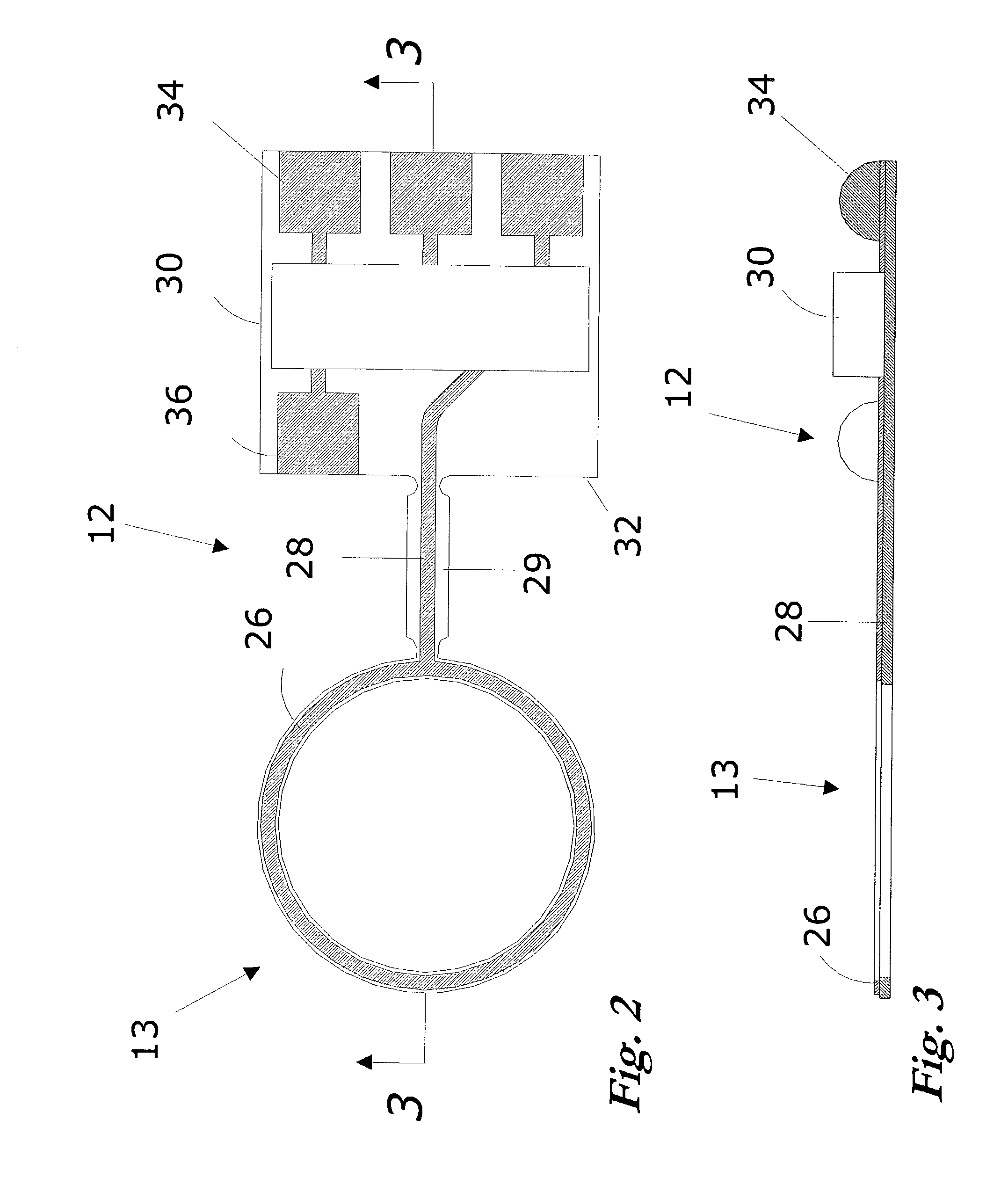
[0035]FIG. 1 illustrates a microphone cartridge 10 having a spacer subassembly 12 made of a flexible printed circuit board material, i.e., flex-print. The spacer subassembly 12, which has an annular shape spacing section 13, separates a diaphragm subassembly 14 from a backplate subassembly 16. The flex-print (e.g., polyimide) can have a thickness in the range of 25 to 50 microns, which is about the size of separation that is needed between the diaphragm subassembly 14 and the backplate subassembly 16. The diaphragm subassembly 14 includes a thin, moveable metallized (polymer) diaphragm 18 that is mounted on a frame 20. The backplate assembly 16 includes a rigid base layer 22 and a charged dielectric layer 24, which may be a TEFLON® fluoropolymer coating having a surface charge or a layer of special electret film (“EMFi”), such as one disclosed in U.S. Pat. Nos. 4,654,546 and 5,757,090 to Kirjavinen, both of which are incorporated herein by reference in their entireties. In essence, ...


PUM


Abstract

In a microphone cartridge, a flexible printed circuit board serves two functions, separating the diaphragm and backplate, and electrically connecting the cartridge and the buffer amplifier. The flex-print includes a spacer portion that maintains the appropriate distance between the diaphragm and backplate, and an integral lead portion having a conductor serving as the signal path for transmitting the signal from the cartridge to the amplifier. The spacer portion has a conductor that electrically contacts the diaphragm or backplate and is connected to the conductor of the integral lead portion. The integral lead portion may optionally include a second electrical conductor providing a reference path from the cartridge to the amplifier. Further, the flex-print may be used as the carrier for the amplifier, its associated circuitry, and for other circuitry within the listening device. And, the flex-print may be used as a portion of the diaphragm subassembly and/or the backplate subassembly

Description

RELATED APPLICATION[0001]This application claims the benefit of priority of U.S. Provisional Patent Application No. 60 / 327,806, filed Oct. 9, 2001.FIELD OF THE INVENTION[0002]This invention relates generally to electroacoustic transducers and, in particular, to an electroacoustic transducer having a flexible printed circuit board on which the internal components of the transducer are mounted.BACKGROUND OF THE INVENTION[0003]Electroacoustic transducers, which convert electrical energy into sound energy and vice versa, have been known for decades. They are useful for various purposes, including telecommunications equipment and hearing instruments, such as hearing aids (or generally “listening devices”) that are located outside the ear or that fit within the ear canal. A conventional listening device includes a miniature microphone that receives acoustic waves and converts the acoustic waves to an audio signal. That audio signal is then processed (e.g, amplified) and sent to the receiv...

Claims


Application Information

Patent Timeline
IPC IPC(8): H04R9/08H04R25/00H04R19/01H05K1/18
CPCH04R19/016H05K1/189
Inventor DE BLOK, MARCELLAFORT, ADRIANUS M.DE ROO, DION I.
Owner SONION NEDERLAND
Why Eureka
Try Eureka