
Sensors carrier for in-tube inspection scraper

a technology of in-tube scraper and sensor carrier, which is applied in the direction of mechanical measuring arrangement, mechanical roughness/irregularity measurement, instruments, etc., can solve the problems of limiting the linear resolution of the inspection scraper with such a carrier, limiting the use of the above devices, and limiting the linear resolution

Inactive Publication Date: 2007-07-10
WEATHERFORD TECH HLDG LLC +1
View PDF41 Cites 50 Cited by
  • Summary
  • Abstract
  • Description
  • Claims
  • Application Information

AI Technical Summary

Benefits of technology

The patent text describes a sensor carrier for an in-tube inspection scraper that improves the detection of flaws in pipelines. The carrier includes a plurality of interconnected ring-shaped sensor supports that are positioned along the inner surface of the pipeline. The sensor supports are elastically connected to each other and can separate their functions of pressure and enveloping the defects in the pipe. The carrier is designed to be compact and easily reeved through pipe turns and narrowing sections. The technical effect of the invention is to enhance the efficiency of flaw detection in pipelines with defects of geometry.

Problems solved by technology

The use of the above devices does not allow one to obtain a resolution sufficient for identification of defects such as pinpoint corrosion or cracks in the pipeline wall.
The main disadvantage of such a carrier is that when it passes a pipeline section with a defect of geometry, for example, a dent, the sensor supports behave as rigid elements, and a knock of the front part of the support against a dent (projection on the pipeline internal surface) is accompanied by a departure of whole support from the non-deformed part of the pipeline.
The basic disadvantage of such a carrier is that the carrier sensors are arranged as a single belt, and since some distance separates the sensors from each other, this distance restricts the linear resolution of the inspection scraper with such a carrier.
Furthermore, the distance between the adjacent sensors cannot be less than the sensor size / and this also restricts the linear resolution.
Besides, when the carrier passes pipeline sections having major defects of the geometry in the cross section, the sensors move away from the non-deformed part of the pipeline near the defect of geometry and this is followed by a collapse of the sleeve with sensors.
When testing the pipeline consisting of pipes having essentially different thickness of the pipe walls, for example, in the presence of earlier repaired pipeline sections, on the sections with an increased wall thickness, as well as in the presence of a fixed foreign object on the internal pipe surface, the movement of the sensor carrier can be accompanied by a collapse of the sleeve and a loss of orientation of some sensors.
Besides, installation of the sensors outside results in a damage of the sensors by such obstacles as jar washers.
The disadvantage of such a carrier is that the elastic sleeve carrying a large number of sensors with associated cables (which provide high linear resolution) or utilization of heavy sensors (for example, magnetic) with long length and low thickness of the sleeve and, respectively, good elasticity, results in deformation of the elastic sleeve under the total weight of the sensors and cables.
This leads to a formation of a gap between the sensors at the top part of the elastic sleeve and the internal surface of the pipeline, in which case the presence of a gap interferes with uniform pressure of the sleeve to the internal wall of the pipe when filling the starting chamber with fluid to be conveyed.
The increase of the sleeve rigidity (to avoid the above phenomenon) is accompanied by a loss of elasticity of the sleeve when enveloping the defects of geometry of the pipeline and formation of gaps between the sensors and the internal surface of the pipeline near the defect.
Besides, the gaps between the sensors and the internal surface of the pipeline are also formed when enveloping the defects of geometry by the sensors arranged at the front wall of the sleeve whose ability of compressing in the plane passing through an carrier axis is much lower than at the section of the sleeve remote from its front wall.

Method used


Image

  • Sensors carrier for in-tube inspection scraper
  • Sensors carrier for in-tube inspection scraper
  • Sensors carrier for in-tube inspection scraper

Examples


Embodiment Construction

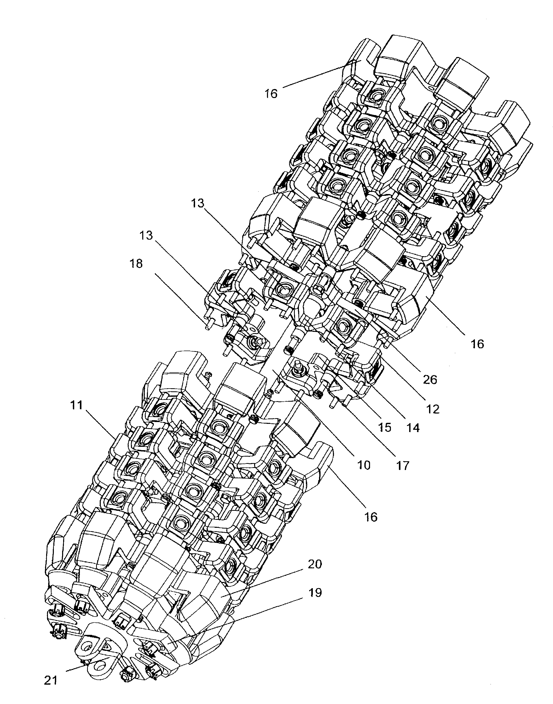
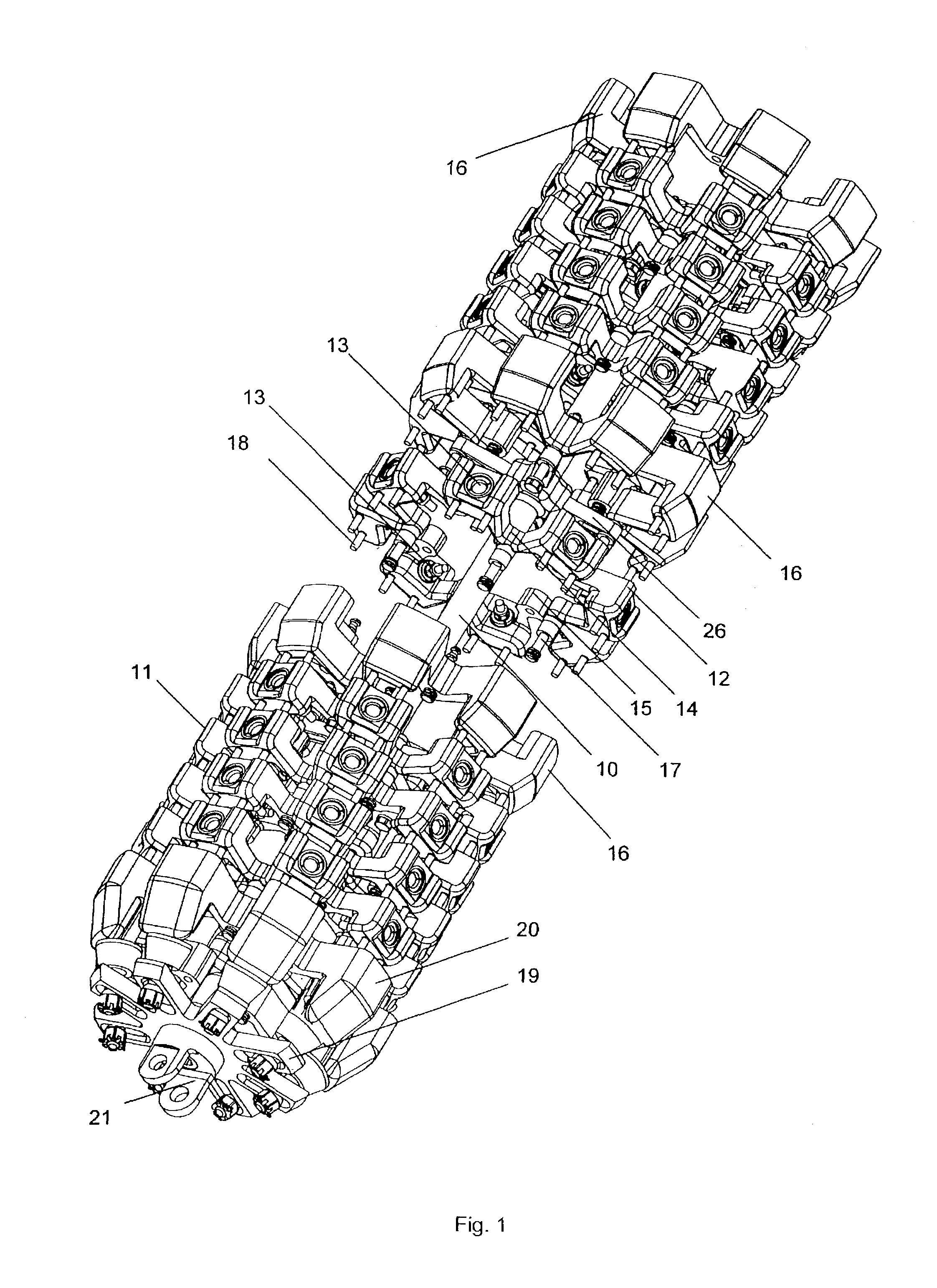
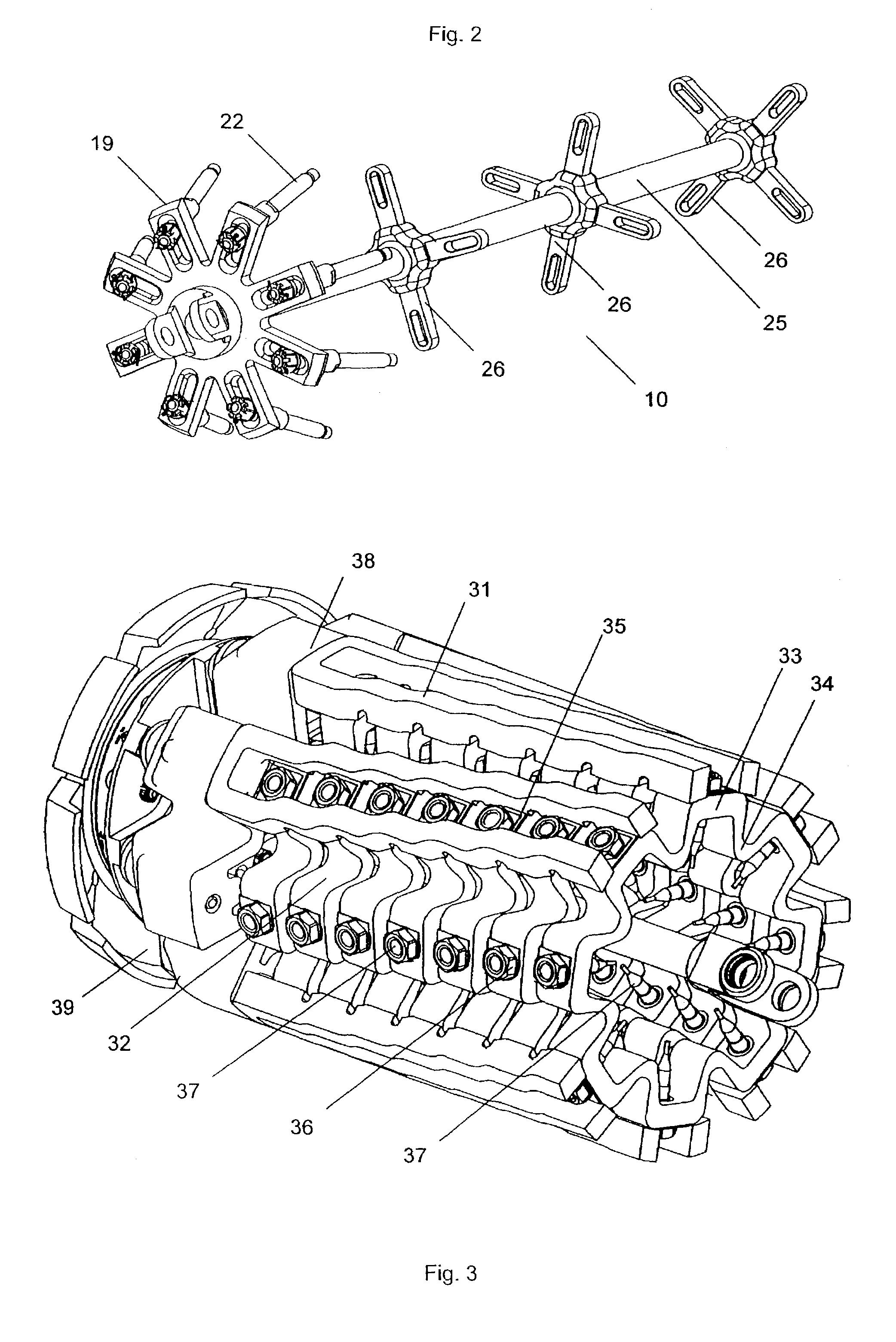
[0117]As a result of solving the technical problem of increasing the efficiency of the flaw detection of long distance pipelines, in-tube flaw detectors (in-tube inspection scrapers) for testing oil pipelines, gas pipelines and condensate pipelines with a nominal diameter from 10″ to 56″ have been developed. As a rule, the in-tube inspection scraper includes one or several sections forming explosion-proof shells and a sensor carrier. The shells accommodate a power supply and electronic equipment for measurements, processing and storage of the obtained measurement data in an onboard computer controlling the scraper operation during its travel inside the pipeline. The scraper housing has polyurethane sleeves centering the inspection scraper inside the pipeline and providing its movement by a flow of fluid conveyed through the pipeline, as well as odometers metering the distance passed inside the pipeline. The information on the length of the passed way measured by the odometers with b...


PUM

PropertyMeasurementUnit
angleaaaaaaaaaa
angleaaaaaaaaaa
angleaaaaaaaaaa

Abstract

A sensor carrier for an in-tube inspection scraper has setting places for installation of monitoring sensors responsive to any diagnostic parameters of a pipeline being inspected. The carrier includes a set of kinematically interconnected sensor supports that are subjected to an elastic force in the radial direction from the carrier axis. The supports are made as elastic ring-shaped elements or as rows of interconnected elements adjoining the pipe wall or are fixed on elastic components such as rings or sectors of sleeves, and / or are connected to a housing capable of bending. Installed on the supports between the sensors and the internal surface of the pipeline are elastic gaskets. The carrier allows one to increase the efficiency of the flaw detection in pipelines having defects of geometry in the cross section.

Description

CROSS-REFERENCES TO RELATED APPLICATIONS[0001]Not Applicable.STATEMENT REGARDING FEDERALLY SPONSORED RESEARCH[0002]Not Applicable.BACKGROUND OF THE INVENTION[0003]1. Field of the Invention[0004]The invention relates to devices used for flaw detection of long-distance pipelines, mainly oil and gas pipelines through non-destructive methods by passing inside the pipeline an intelligent scraper with monitoring sensors mounted thereon and responding to any diagnostic parameter of the pipeline. The invention primarily relates to means for attaching sensors and maintenance of their necessary spatial location with respect to the pipeline surface during the travel of the scraper.[0005]2. Description of the Related Art[0006]Known in the art are sensor carriers (see GB939172, U.S. Pat. Nos. 3,496,457, 3,449,662, 3,810,384, 3,835,374, 3,940,689, 3,949,292, 3,967,194, 3,973,441, GB2020023, U.S. Pat. Nos. 4,342,225, 4,457,073, 1,157,443, 4,717,875, 4,598,250, DE3506622, DE3706660, U.S. Pat. No. 4...

Claims


Application Information

Patent Timeline
Patent Type & Authority Patents(United States)
IPC IPC(8): G01M19/00G01B5/00F16L55/26F16L55/28F17D5/00F17D5/06G01B5/28G01M99/00G01N29/04
CPCF16L55/28G01N2291/02827
Inventor SAPELNIKOV, URIY A.KOZYREV, BORIS V.MATVEEV, MIKHAIL S.CHERNOV, DMITRY G.ELISEEV, VLADIMIR N.
Owner WEATHERFORD TECH HLDG LLC
Learn More