Cantilevered stator stage

a stator stage and cantilever technology, applied in the direction of stators, machines/engines, liquid fuel engines, etc., can solve problems such as difficulty in achieving, and achieve the effect of reducing thickness, reducing thickness, and facilitating abrasion

Active Publication Date: 2007-07-10
ROLLS ROYCE PLC
View PDF7 Cites 32 Cited by
  • Summary
  • Abstract
  • Description
  • Claims
  • Application Information

AI Technical Summary

Benefits of technology

[0007]The tips of the stators may be formed so as to facilitate abrasion thereof. The stators may have a reduced

Problems solved by technology

This can be difficult to achieve due for instance to vari

Method used


Image

  • Cantilevered stator stage
  • Cantilevered stator stage
  • Cantilevered stator stage

Examples


Embodiment Construction

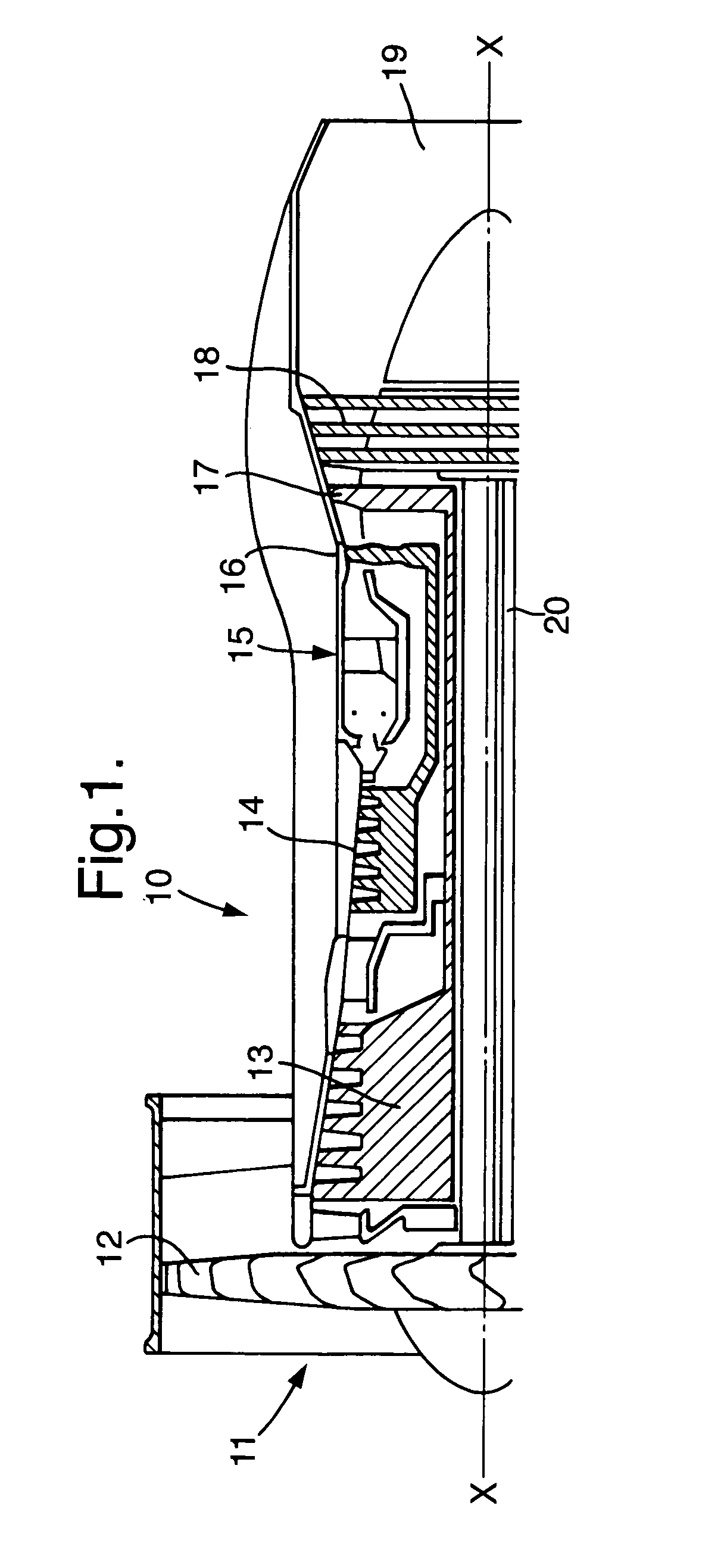
[0026]Referring to FIG. 1, a gas turbine engine is generally indicated at 10 and comprises, in axial flow series, an air intake 11, a propulsive fan 12, an intermediate pressure compressor 13, a high pressure compressor 14, combustion equipment 15, a high pressure turbine 16, an intermediate pressure turbine 17, a low pressure turbine 18 and an exhaust nozzle 19.

[0027]The gas turbine engine 10 works in a conventional manner so that air entering the intake 11 is accelerated by the fan 12 which produces two air flows: a first air flow into the intermediate pressure compressor 13 and a second air flow which provides propulsive thrust. The intermediate pressure compressor compresses the air flow directed into it before delivering that air to the high pressure compressor 14 where further compression takes place.

[0028]The compressed air exhausted from the high pressure compressor 14 is directed into the combustion equipment 15 where it is mixed with fuel and the mixture combusted. The res...


PUM

PropertyMeasurementUnit
Lengthaaaaaaaaaa
Thicknessaaaaaaaaaa
Areaaaaaaaaaaa

Abstract

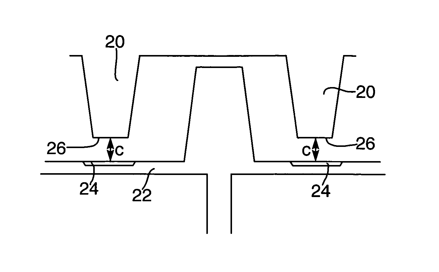
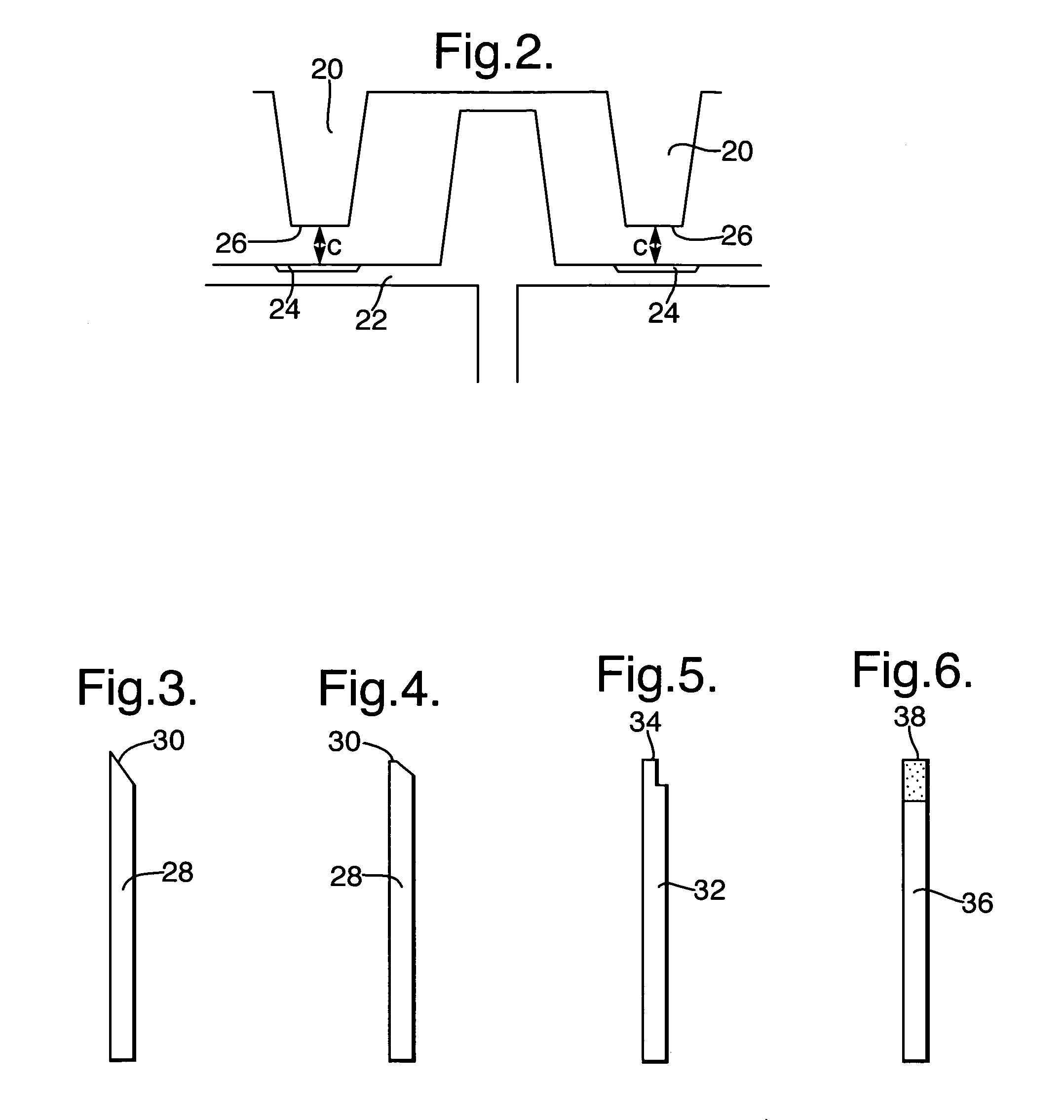
A cantilevered stator stage for the axial compressor 14 of a gas turbine engine 10 in which the stator tips 26 rub against an abrasive section 24 on the rotor drum 22 during initial running of the engine 10 to abrade the tips 26 of the stator to provide optimised stator tip running clearance.

Description

FIELD OF THE INVENTION[0001]This invention relates to cantilevered stator stages, and axial compressors and turbines including such stages for gas turbine engines. The invention also relates to a method of building an axial compressor or turbine for a gas turbine engine and also a method of optimising cantilever stator tip clearance in such an axial compressor or turbine.BACKGROUND OF THE INVENTION[0002]In gas turbine engines it is generally desirable for efficient operation to maintain minimum rotor tip clearances, and preferably with a substantially constant clearance around the circumference. This is the position for instance with cantilevered stators in an axial compressor or turbine. This can be difficult to achieve due for instance to various asymmetric effects either on build or during running. These effects include the casing centre being offset relative to the rotor drum centre line during build and / or during running. The casing may be distorted from a circular shape during...

Claims


Application Information

Patent Timeline
IPC IPC(8): F01D11/12F01D11/02F01D9/04F02C7/28F04D29/10
CPCF01D5/20F01D5/284F01D9/04F01D11/001F01D11/122F04D29/023F04D29/083F04D29/164F04D29/321F04D29/542F05D2230/41F05D2250/192F05D2300/611
Inventor LEWIS, LEO V
Owner ROLLS ROYCE PLC
Why Eureka
Try Eureka