Module battery

a module battery and battery body technology, applied in the field of modules, can solve the problems of troublesome connection work, shorten the life cycle of the module battery, and troublesome connection work for the electrode tabs and the associated wirings, and achieve the effect of effective heat dissipation and easy assembly

Active Publication Date: 2007-07-10
ENVISION AESC JAPAN LTD
View PDF11 Cites 18 Cited by
  • Summary
  • Abstract
  • Description
  • Claims
  • Application Information

AI Technical Summary

Benefits of technology

[0010]The present invention has been completed to address such issues encountered in the related art and has an object to provide a module battery which is easy to assemble; enabled to encapsulate a sub-assembly body in a module case with no looseness, and which is able to protect electrode tabs from motes of dust while providing effective heat dissipation.

Problems solved by technology

However, the use of the sub-assembly body formed by connecting large numbers of cells to the associated wirings in the manner mentioned above involves troublesome connection work for the respective cells and the associated electrode tabs, and troublesome connection work for the electrode tabs and the associated wirings.
Specifically, this looseness of the stack battery in the module case causes the cells and connecting areas between the cell and the associated wirings to encounter excessive load, resulting in a shortened life cycle for the module battery.
Furthermore, when large numbers of cells are combined in the manner described above, adequate heat dissipation is required.
In this case, ventilating atmospheric air into the module case results in undesirable consequences, such as motes of dust accumulating on the electrode terminals (a positive electrode terminal and a negative electrode terminal), resulting in the probability of short-circuits.

Method used


Image

  • Module battery
  • Module battery
  • Module battery

Examples


first embodiment

[0047

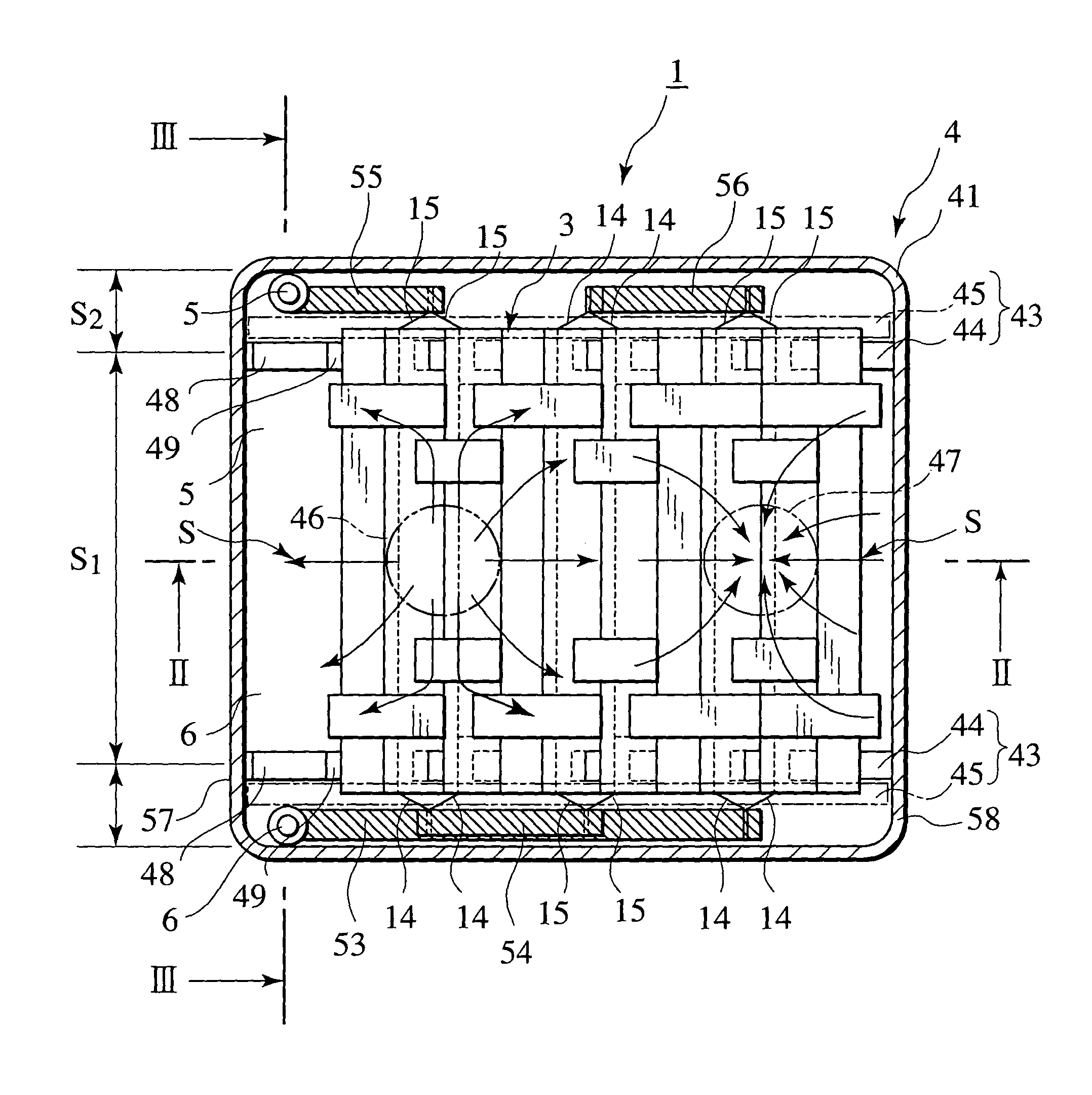
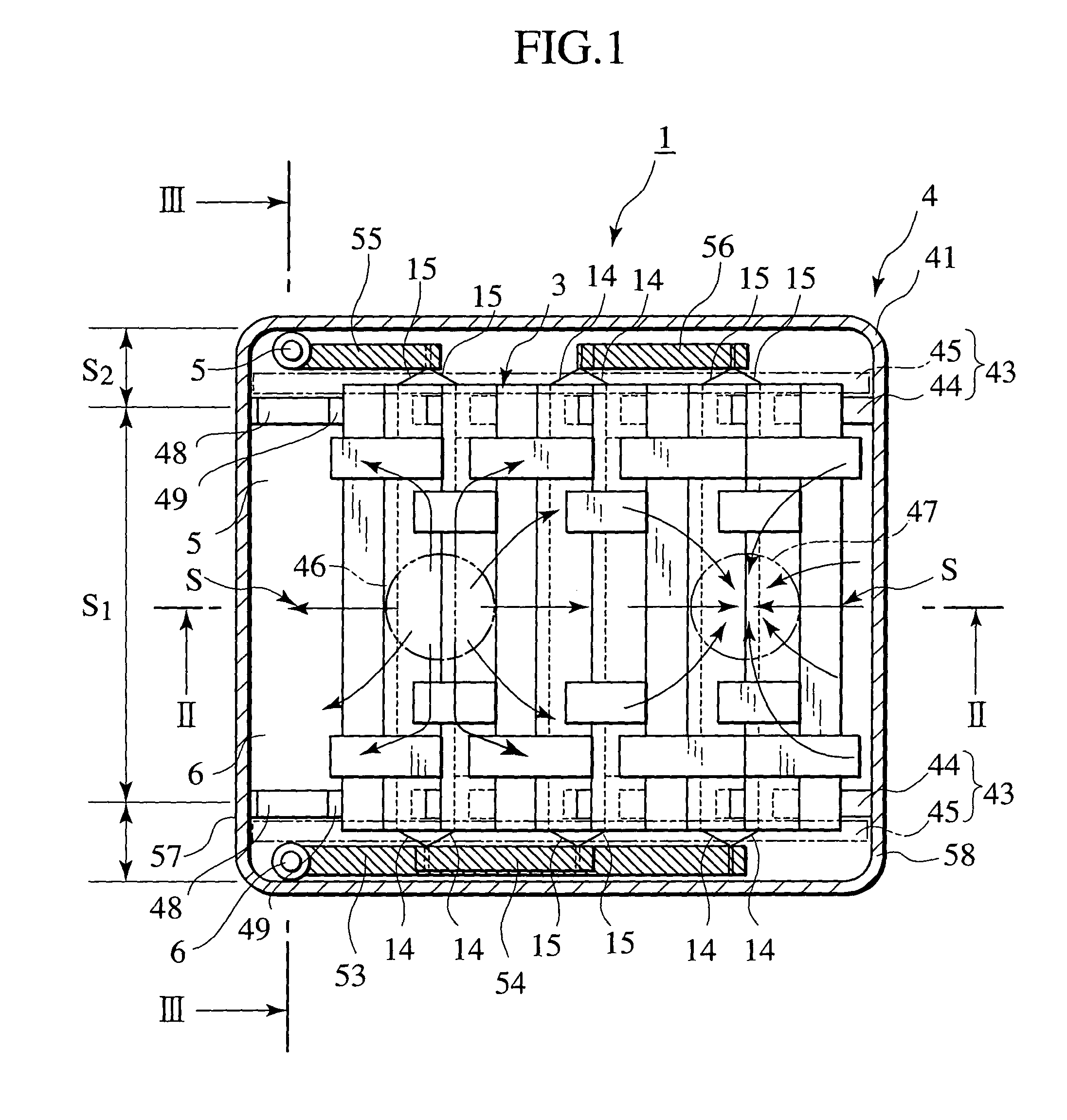
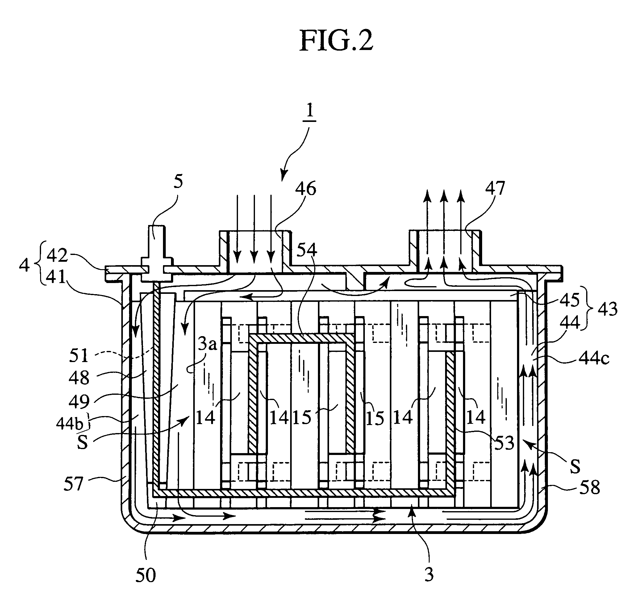
[0048]FIGS. 1 to 9 show a first embodiment of the present invention. As shown in FIGS. 1 to 4, a module battery 1 of the first embodiment is comprised of a basic structure constructed of a stacked body 3 (a sub-assembly body) formed in a multi-staged stack of cell holders 2 on each of which a cell 10 is mounted and held, and a module case 4 in which the stacked body 3 is encapsulated. A group of cells 10 inside the stacked body 3 are connected to input and output terminals 5, 6 in series and / or parallel through wirings 51, 52 and bus bars 53, 54, 55, 56, with charging and discharging cycles being performed via the input and output terminals 5, 6.

[0049](Stacked Body)

[0050]As shown in FIGS. 1 to 4, the stacked body 3 has a basic structure constructed from the multi-staged stack of the cell holders 2 (see FIGS. 6A to 6E) on each of which the cell 10 is mounted and held. In the present embodiment, with a view to providing an improved heat dissipating property, plate-shaped heat sin...

second embodiment

[0107

[0108]FIGS. 13A to 15 show a second embodiment. The same component parts as those of the first embodiment bear the same reference numerals to omit redundant description.

[0109]As shown in FIGS. 13A to 15, a cell holder 30 of the second embodiment is formed with an vertical wall 31 that protrudes, in a direction in which the cell holders 30 are stacked, so as to surround a mounting surface 23 of a frame section 21 of the cell holder 30. The vertical wall 31 is formed with notched portions 32, at positions in compliance with the electrode tabs 14, 15 of the cell 10. The electrode tabs 14, 15 are enabled to be exposed through the notched portions 32 to the outside of the cell holder 30. As shown in FIG. 15, an inner side surface 31b of the vertical wall 31 is held in abutting engagement with the outer peripheral edge of the cell 10 and serves as a sealing surface to restrict the electrolyte from leaking from the joined portion 10b of the cell 10.

[0110]Further, in the second embodim...

third embodiment

[0112

[0113]FIGS. 16 and 17 show a third embodiment. The same component parts as those of the first embodiment bear the same reference numerals to omit redundant description.

[0114]As shown in FIGS. 16 and 17, a module cell 100 of the third embodiment differs from the first embodiment in that a rib component 45, forming a partition wall, is formed with communicating ports 101 (communicating portion), that form a communicating section, through which communication is established between a ventilation space Si and electrode tab exposure spaces S2, S3, with each air filter 102 being covered on each communicating port 101.

[0115]According to the module cell 100 of the third embodiment, since the rib component 45 forming the partition walls (44, 45, 48, 49, 50) is formed with the communicating ports 101 to provide communication between the ventilation space S1 and the electrode tab exposure spaces S2, S3 to allow the communicating ports 101 to be covered with the air filters 102, a further i...


PUM

PropertyMeasurementUnit
temperatureaaaaaaaaaa
particle sizeaaaaaaaaaa
specific surface areaaaaaaaaaaa

Abstract

A module battery comprises cells each having an electric power generating element hermetically sealed in a package film, and cell holders on each of which each of the cells is mounted and held. The cell holders are formed in configurations so as to allow the cell holders to be freely stacked in a plurality of stages while permitting the cells to be retained thereon and to allow electrode tabs of the cells to be exposed between the cell holders neighboring in a stacking direction. Thus, the module battery can be formed in an easy assembly work.

Description

BACKGROUND OF THE INVENTION[0001]1. Field of the Invention[0002]The present invention relates to a module battery composed of a plurality of stack type cells having stacked electrodes, serving as an electric power generating element, which are hermetically sealed in package films.[0003]2. Description of the Related Art[0004]Recently, there has been increasing worldwide concern regarding air pollution caused by exhaust gases emitted from automobiles, and attention has been greatly focused on an electric vehicle propelled by a prime power source generating an electric power output, and a hybrid car combined with an engine and an electric motor. Research and development establishments working on such a high power output type battery for use in these vehicles are sharing important industrial positions.[0005]Regarding such a high power output battery, a module battery has been developed that is comprised of a plurality of cells each with a high energy density and high power output, such ...

Claims


Application Information

Patent Timeline
Patent Type & Authority Patents(United States)
IPC IPC(8): H01M2/24H01M10/50H01M2/08H01M50/529H01L25/00H01M4/48H01M4/52H01M50/105H01M50/211H01M50/271H01M50/291H01M50/296H01M50/507
CPCH01M2/02H01M2/1011H01M2/1077H01M2/204H01M10/5004H01M10/5016H01M10/5055H01M10/5059H01M10/5063H01M4/485H01M4/525Y02T10/7011H01M10/0525H01M10/625H01M10/6557H01M10/6555H01M10/6561H01M10/613Y02E60/10H01M50/256H01M50/271H01M50/105H01M50/296H01M50/211H01M50/507H01M50/291
Inventor OOGAMI, ETSUO
Owner ENVISION AESC JAPAN LTD
Why Eureka
Try Eureka