Charged particle beam apparatus

a particle beam and apparatus technology, applied in the field of chargeable particle beam apparatus, can solve the problems of uneven or dispersed adjustment values, more time consumed, and many time required for introducing a function, so as to reduce the time consumed to find out a function during the new design of the apparatus, and eliminate the time/technical restrictions imposed on operation per se.

Inactive Publication Date: 2007-07-10
HITACHI HIGH-TECH CORP
View PDF7 Cites 8 Cited by
  • Summary
  • Abstract
  • Description
  • Claims
  • Application Information

AI Technical Summary

Benefits of technology

[0009]An object of the present invention is to provide a charged particle beam apparatus capable of dealing with the above problems and performing highly accurate condition setting easily within a short period of time.
[0010]More specifically, this invention intends to provide a charged particle beam apparatus incorporating a setting method which can perform highly accurate setting while eliminating temporal / technical restrictions imposed on optical condition setting and dispensing from comparison with actual images and which can be immune to the influence of apparatus change and new apparatus development.
[0012]Advantageously, this invention can provide a charged particle beam apparatus capable of performing highly accurate condition setting easily within a short period of time.
[0019]Especially, by using such a calculation means as simulator, temporal / technical restrictions imposed on operation per se can be eliminated. By sufficiently introducing differences in products of the charged particle beam apparatus into the memory means for storing the shape and position of the charged particle optical system, acquisition of an actual image for the sake of confirmation after condition setting can be dispensed with. Further, when making a new design of apparatus, it suffices that only an apparatus structure to be memorized is exchanged, so that the algorithm of condition setting can remain unchanged and time consumed to find out a function during new design of apparatus can be decreased.

Problems solved by technology

But, in the image acquisition method, there needs acquisition of actual images corresponding in number to adjustment items each time that an optical condition is set and the more the adjustment items including preparation of specimens for adjustment and focus adjustment, the more the time is consumed.
On the other hand, in the function method, determination of a function must be done by trial and error in many cases each time an apparatus is designed and for example, in the case of new design of apparatus, much time is required for introducing a function.
Further, even in an apparatus of the same type, adjustment values are uneven or dispersive among a plurality of products of the apparatus and the function needs to be added with parameters for adjusting itself in compliance with individual products of the apparatus.
Furthermore, the parameters are empirical which fail to directly reflect causes of actual unevenness (unevenness in working, assembling and adjustment of parts of the apparatus) and hence, there is a possibility that a difference will occur between a setting value based on the function method and a true setting value.
Accordingly, for ultimate settlement of adjustment values, comparison / confirmation / adjustment is sometimes needed in relation to an actual image and operation becomes complicated and time-consuming.

Method used


Image

  • Charged particle beam apparatus
  • Charged particle beam apparatus
  • Charged particle beam apparatus

Examples


Embodiment Construction

[0026]An embodiment of the present invention will now be described specifically by way of example of a semiconductor circuit pattern defect inspection apparatus based on a scanning electron microscope (hereinafter referred to as SEM type wafer inspection apparatus).

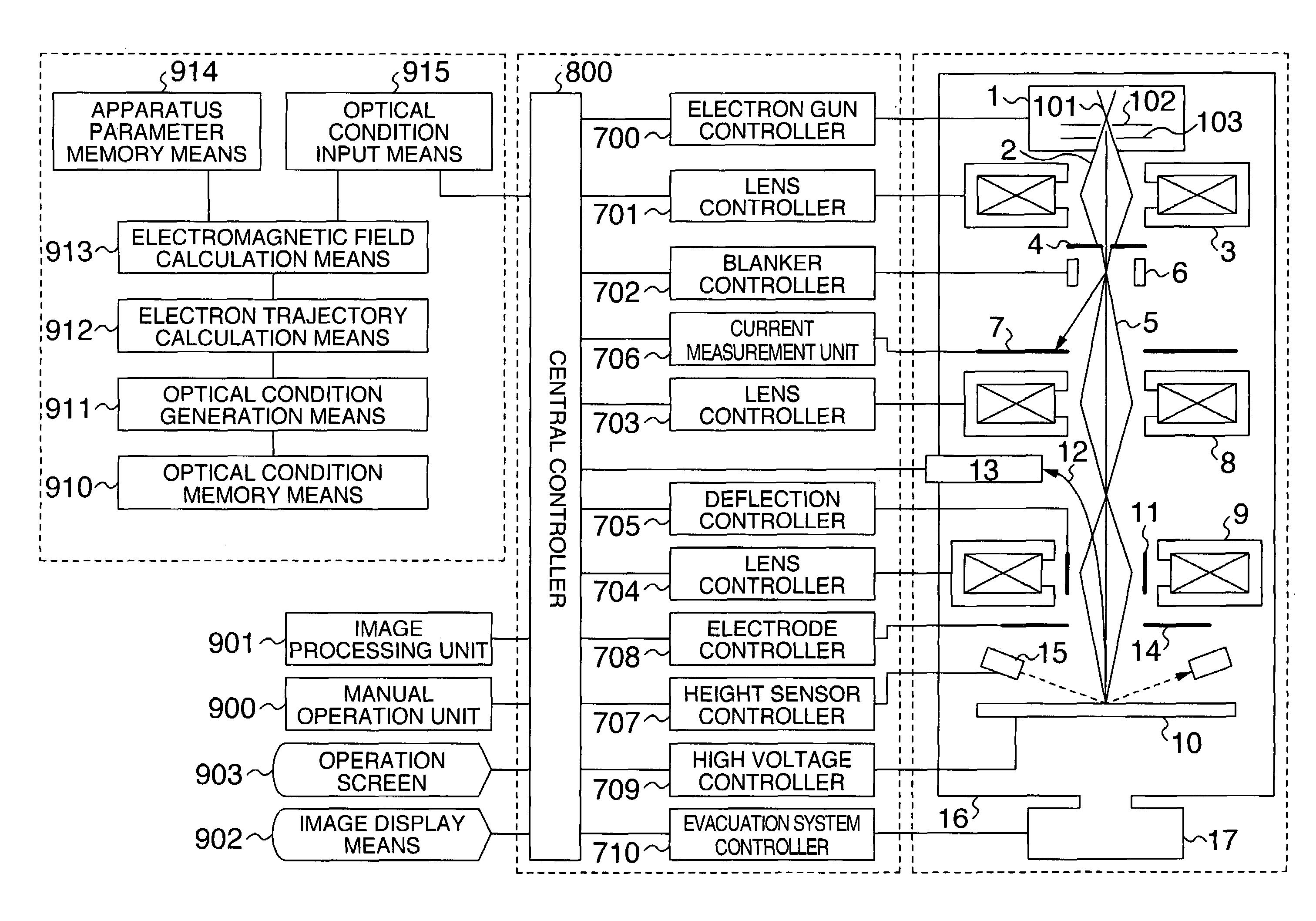
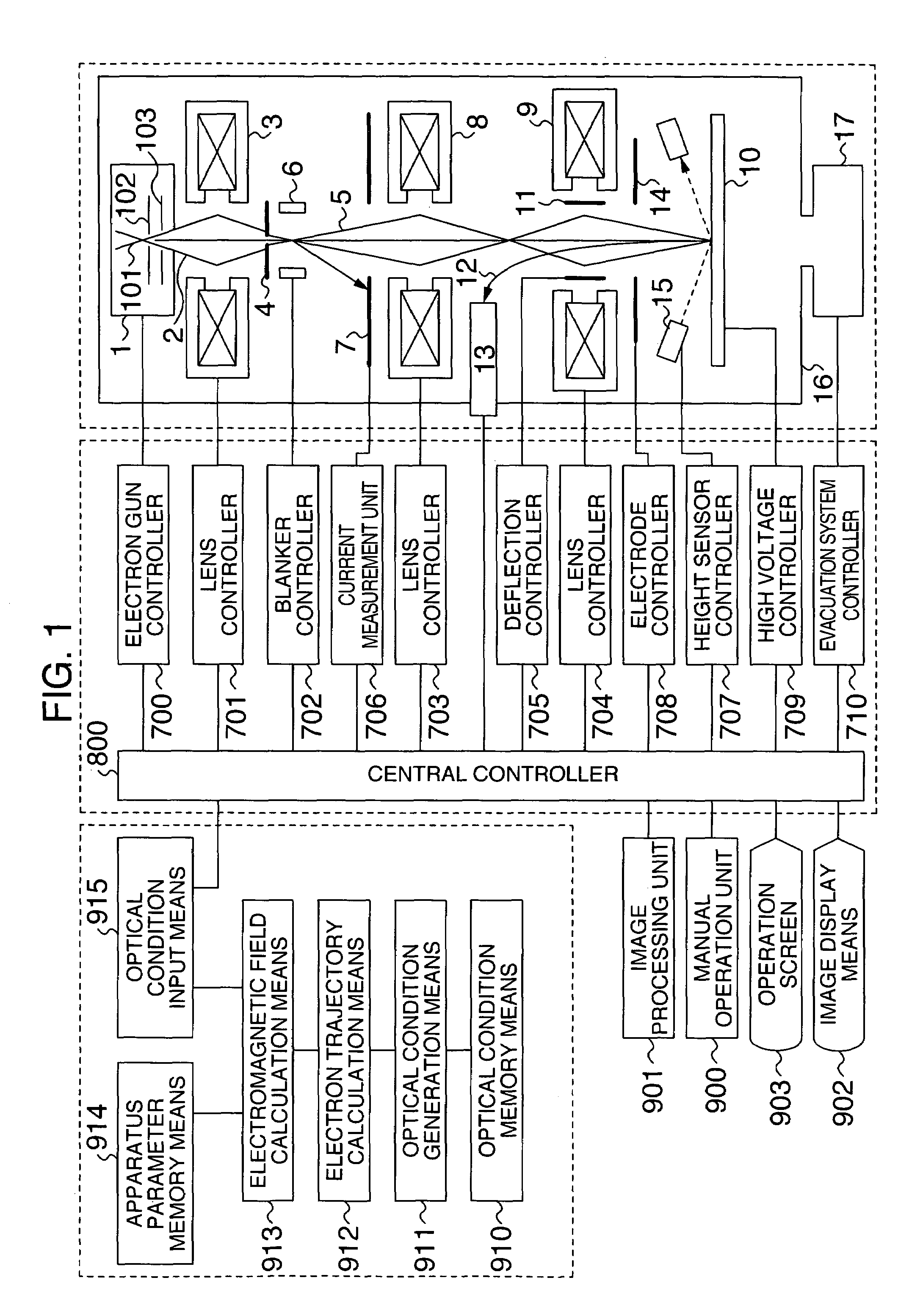
[0027]Referring to FIG. 1, construction of the SEM type wafer inspection apparatus will be described.

[0028]In an electron gun 1 controlled by an electron gun controller 700, an extracting voltage V1 applied across electron source 101 and extracting electrode 102 and thermal energy applied to the electron source 101 cooperate to emit an electron beam 2 representing a charged particle beam.

[0029]The electron beam 2 is accelerated to an outgoing energy level EO=e|Vo| by an accelerating voltage Vo applied to an accelerating electrode 103 so as to be emitted from the electron gun 1. The emitted electron beam 2 is condensed by a first condenser lens 3 controlled by a lens controller 701 and is then admitted through a beam limit...


PUM


Abstract

A charged particle beam apparatus obtains an image by detecting a generation signal inclusively indicative of secondary electrons generated from a specimen. The apparatus has an input unit for inputting current and voltage values to be applied to a charged particle optical system through which the charged particle beam travels, a memory unit for storing shape, position and physical properties of the charged particle optical system and accuracy of the applied current or voltage, an electromagnetic field calculation unit for calculating an electromagnetic field near a path of the charged particle beam, a charged particle trajectory calculation unit for calculating a trajectory of the charged particle beam in the calculated electromagnetic field, a memory unit for storing a result of the trajectory calculation and a controller for controlling the charged particle optical system on the basis of the result of the trajectory calculation.

Description

BACKGROUND OF THE INVENTION[0001]The present invention relates to a charged particle beam apparatus for obtaining an image displayed by irradiating a charged particle beam on a specimen and detecting a generation signal inclusively indicative of secondary electrons generated from the specimen.[0002]A scanning electron microscope (hereinafter simply referred to as SEM) is available as the charged particle beam apparatus for obtaining an image by irradiating a charged particle beam on a specimen and detecting a signal secondarily generated from the specimen. Especially, in a semiconductor wafer inspection apparatus based on the SEM, a semiconductor wafer surface having a large area is observed and therefore an SEM image of high resolution needs to be acquired while maintaining a high throughput. For the sake of acquisition of a high-resolution SEM image, it is necessary that adjustment items of focus, image magnification and image rotation angle as well as dependency of these factors ...

Claims


Application Information

Patent Timeline
Patent Type & Authority Patents(United States)
IPC IPC(8): H01J37/28H01J37/256
CPCH01J37/21H01J37/265H01J37/28H01J2237/216H01J2237/24592H01J2237/2487H01J2237/2817H01J2237/2826
Inventor SUZUKI, MAKOTOTANIMOTO, KENJISASAKI, YUKO
Owner HITACHI HIGH-TECH CORP
Why Eureka
Try Eureka