Engine balancing system and method

a technology of engine balancing and balancing method, which is applied in the direction of computer control, temperatue control, special data processing applications, etc., can solve the problems of shaft misalignment, vibration, and vibration, and achieve the effect of reducing the vibration of the rotating machin

Active Publication Date: 2007-07-10
THE BOEING CO
View PDF4 Cites 21 Cited by
  • Summary
  • Abstract
  • Description
  • Claims
  • Application Information

AI Technical Summary

Problems solved by technology

However, turbo-machines are prone to vibration from the rotating parts (e.g. the compressor and turbine discs of a turbojet).
The vibration arises because often the center of mass of each disc rotating assembly may be slightly displaced from the center of rotation.
Moreover, the shaft may also suffer from slight misalignment and center of mass offsets too.
Thus, when the turbo-machine rotates, these imbalances cause the individual components (the compressor, the turbine, and the shaft) to vibrate.
Differences between the levels of vibration of each part may aggravate the resulting movement of the machine.
The vibration is typically transmitted through the aircraft structure generating corresponding noise and vibration in the cabin of the aircraft.
Such vibration and noise often cause passenger and crew discomfort.
Many other types of turbo-machines, beyond the turbojet engine discussed above, can suffer from the above described drawbacks.

Method used


Image

  • Engine balancing system and method
  • Engine balancing system and method
  • Engine balancing system and method

Examples


Embodiment Construction

[0018]The following description of the preferred embodiment(s) is merely exemplary in nature and is in no way intended to limit the invention, its application, or uses.

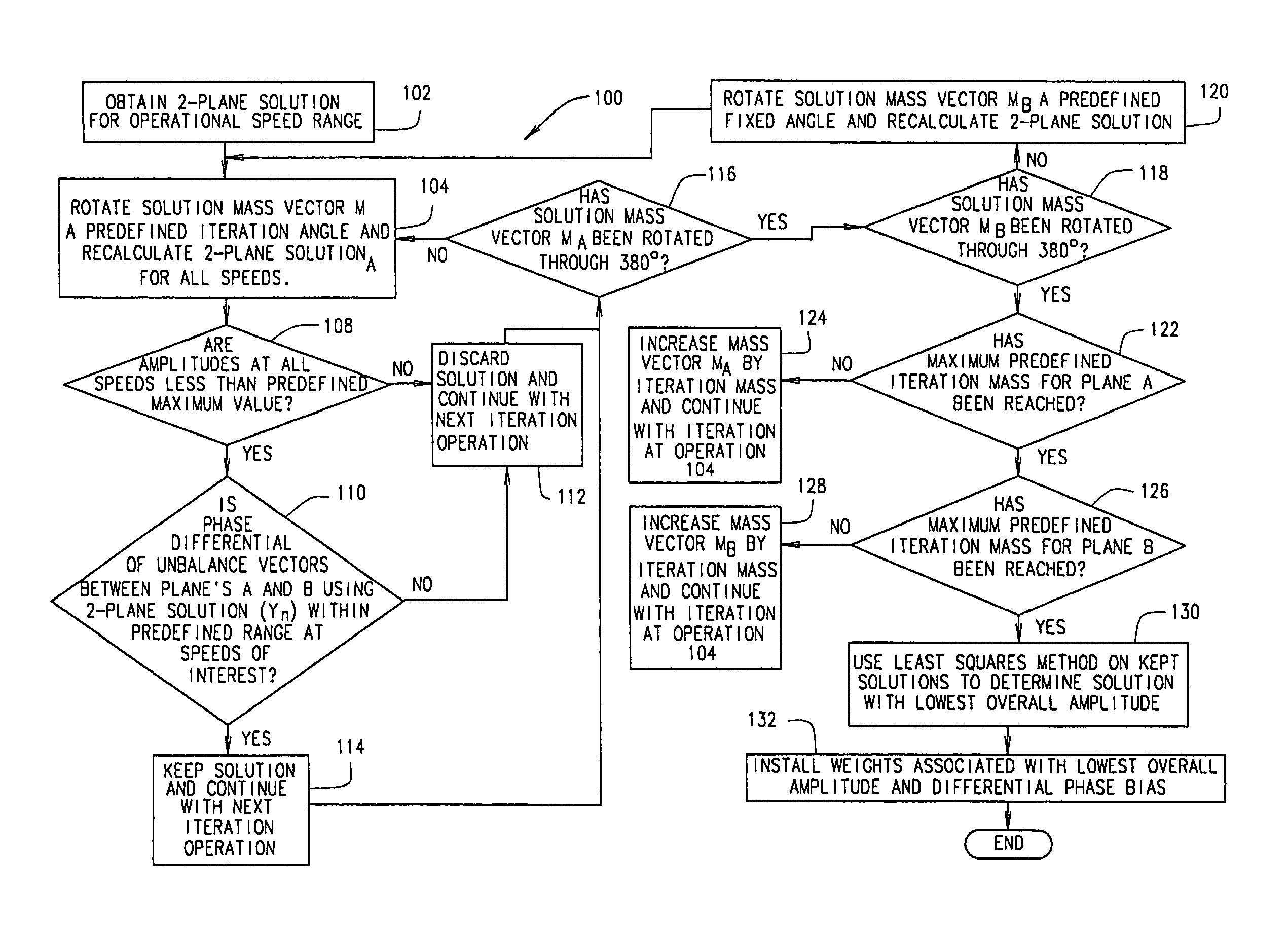
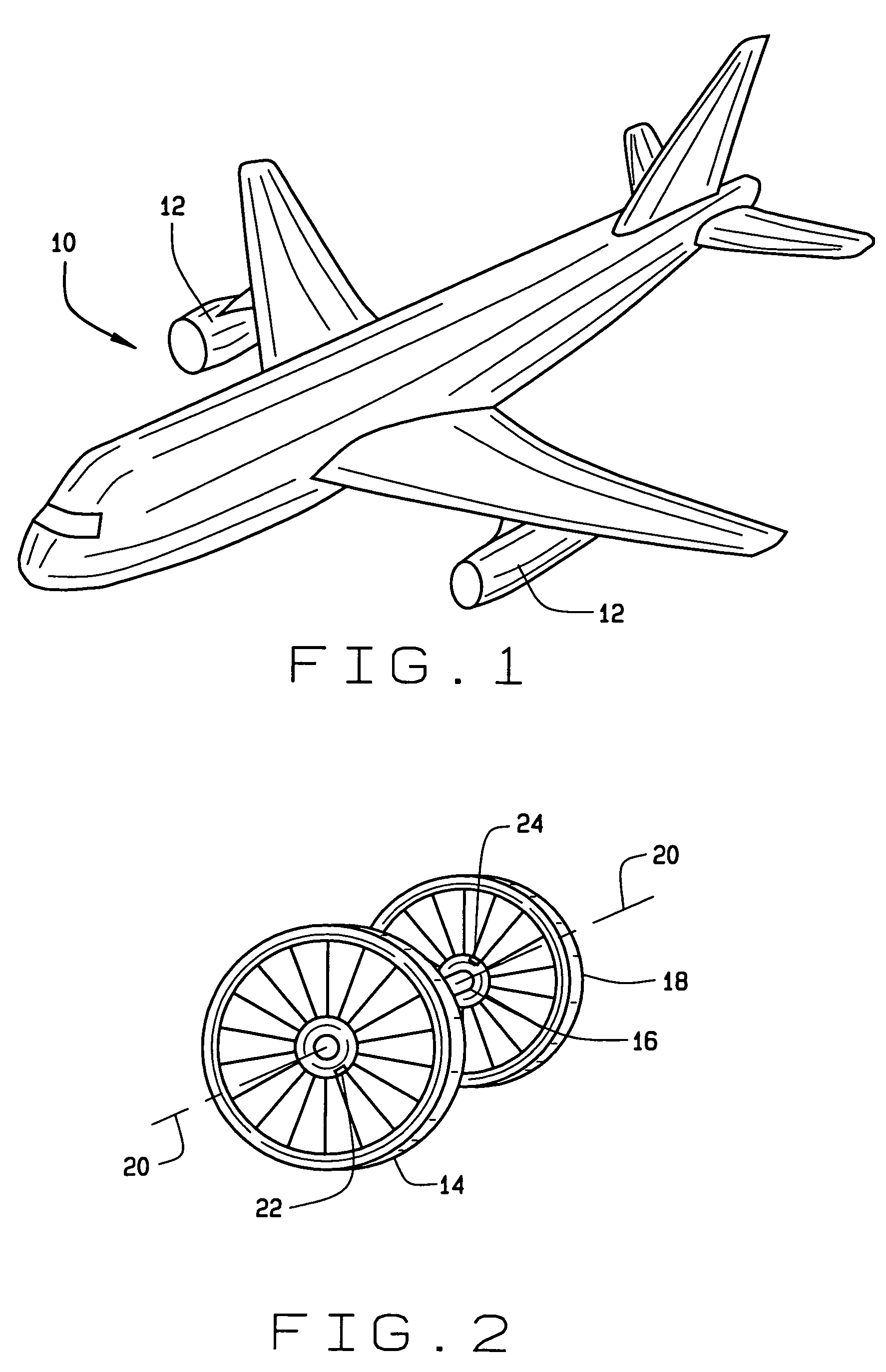
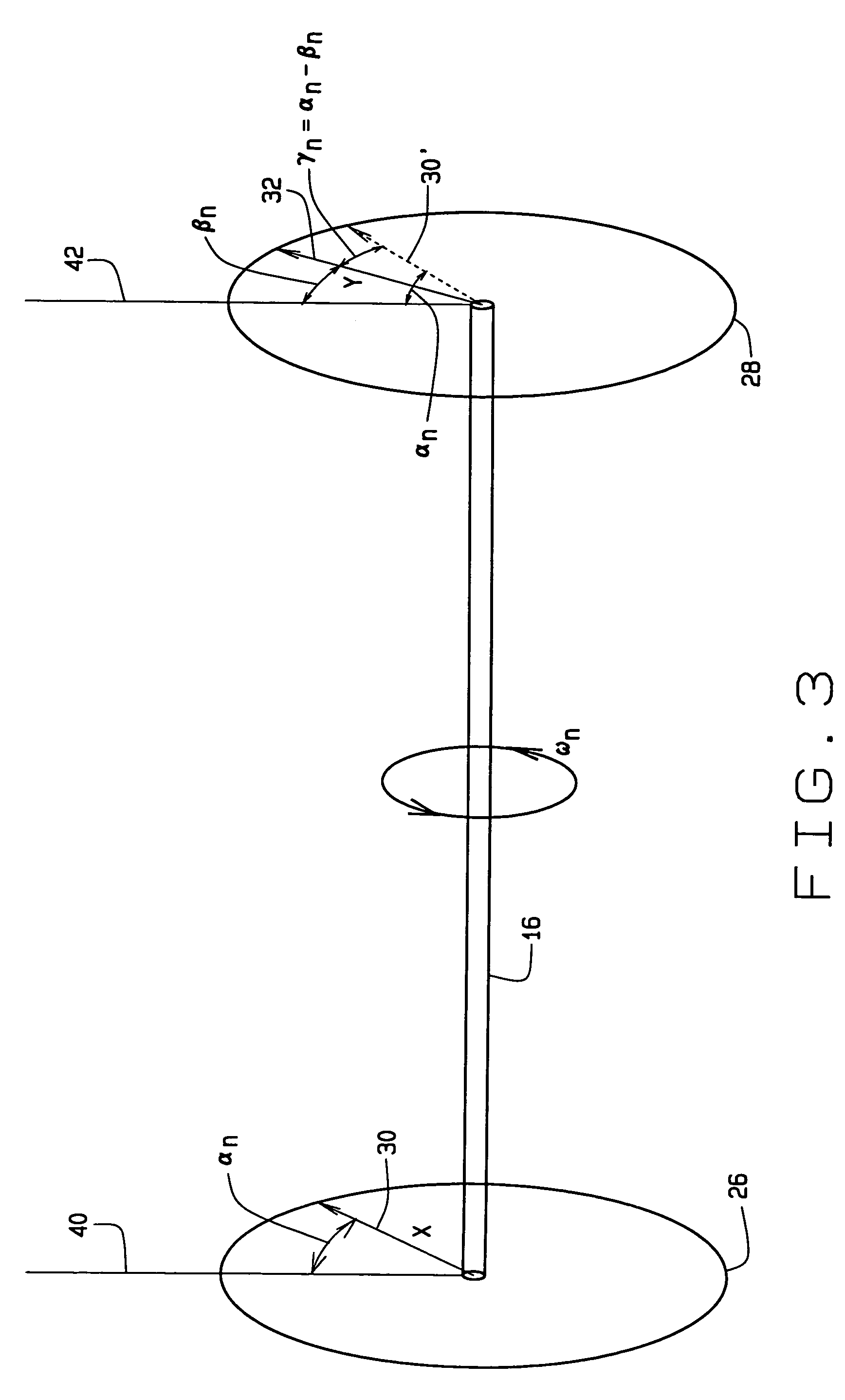
[0019]The present invention provides a system and method for vibration balancing rotating machinery. More particularly, the present invention balances the vibrations at the front and rear of an aircraft jet engine to minimize aircraft interior noise and vibration caused by movement of the engine relative to the aircraft. Preferably the motion of an aircraft engine relative to the remainder of the aircraft, e.g. the aircraft fuselage, produces minimal noise and vibration within a passenger cabin of the aircraft. For example, the lowest noise and vibration for a 737NG aircraft offered by the Boeing Company of Chicago, Ill. occurs when rotation of a fan and a turbine within an engine of the aircraft are about 250 degrees out of phase. However, a preferred phase difference may vary with the speed of the engine. For other ...


PUM


Abstract

A method for balancing vibrations in a rotating machine is provided. The rotating machine has a first and a second plane of imbalance. The method includes determining a first set of solution mass vectors that includes a first solution mass vector for the first plane and a first solution mass vector for the second plane. Each first solution mass vector includes a mass and a phase angle. A first phase difference between a phase angle of the first solution mass vector for the first plane and a phase angle for the first solution mass vector for the second plane is calculated. The first phase difference is compared to a pre-selected value. If the first phase difference is less than the pre-selected value, the first set of solution mass vectors is retained. The first set of solution mass vectors is then incremented to create a second set of solution mass vectors that includes a second solution mass vector for the first plane and a second solution mass vector for the second plane. A second phase difference between a phase angle of the second solution mass vector for the first plane and a phase angle for the second solution mass vector for the second plane is then compared to the pre-selected value. If the second phase difference is less than the pre-selected value, the second set of solution mass vectors is retained. Finally, selected retained solution mass vectors are determined that balance the rotating machine such that vibration of the rotating machine is reduced.

Description

CROSS REFERENCE TO RELATED APPLICATIONS[0001]This application claims the benefit of U.S. Provisional Application No. 60 / 504,303, filed on Sep. 19, 2003. The disclosure of the above application is incorporated herein by reference.FIELD OF THE INVENTION[0002]The present invention relates to vibration balancing of rotating machinery, and more particularly to dynamic vibration balancing of turbojet engines.BACKGROUND OF THE INVENTION[0003]Aircraft employing turbo-machines enjoy higher performance than similar aircraft not equipped with turbo-machinery. For instance, turbojets provide significantly higher thrust at higher speeds and altitudes than the prior art engines. Modern turbojets include a compressor disc mounted on a shaft toward the forward end of the jet engine. The shaft also carries a turbine disc mounted on the aft end of the shaft. In operation, the compressor compresses rarified air drawn into the engine. Then, within a fuel mixing region of the engine, fuel nozzles inject...

Claims


Application Information

Patent Timeline
Patent Type & Authority Patents(United States)
IPC IPC(8): G01H11/00G06F19/00F01D5/02F16F15/32G01M1/22G01M1/36
CPCF01D5/027G01M1/22G01M1/32F05D2260/96
Inventor SKILTON, TIMOTHY L
Owner THE BOEING CO
Why Eureka
Try Eureka