Methods and apparatus for reducing electromagnetic signal noise

a technology of electromagnetic signal and method, applied in the field of wireless data transmission systems, can solve the problems of reducing the operating clearance of other operations, damage to the cable, and inability to use wireline systems in general, and achieve the effect of reducing nois

Active Publication Date: 2007-07-10
WEATHERFORD TECH HLDG LLC
View PDF69 Cites 48 Cited by
  • Summary
  • Abstract
  • Description
  • Claims
  • Application Information

AI Technical Summary

Benefits of technology

[0013]Methods and apparatus are provided for reducing noise in a detected electromagnetic wave used to telemeter data during a wellbore operation. In one embodiment, two surface antennae are placed on opposite sides of the wellbore and at the same distance from the wellbore. The signals from the two antennae are summed to remove the noise in the electromagnetic signal transmitted from the electromagnetic downhole tool.
[0015]In another embodiment still, a method for reducing noise in a telemetry system includes measuring a first signal from a first location away from a wellbore and measuring a second signal from a second location away from the wellbore, wherein the first location and the second location are substantially the same distance from the wellbore and at opposite sides of the wellbore. Thereafter, the first signal and second signal are summed. In another embodiment, the method also includes measuring a third signal from a third location proximate the wellbore and calculating a potential difference between the third signal and the summed first and second signals. Preferably, the telemetry system transmits information in the form of an electromagnetic wave.
[0019]In another embodiment still, a telemetry system is provided for reducing noise from a rotating tubular during communication of data from a sensor located in a wellbore. The telemetry system includes a transmitter disposed proximate the sensor for transmitting the data; a first receiver located at a distance away from the wellbore; a second receiver located near the wellbore; and a third receiver adapted to detect a magnetic signal generated from a rotating tubular. In another embodiment, the telemetry system further includes a phase processor for adjusting a phase of the detected magnetic signal and / or an amplitude processor for adjusting an amplitude of the detected magnetic signal. In another embodiment, the first receiver and the second receiver are adapted to detect an electromagnetic wave.
[0020]In another embodiment still, a method of reducing noise during communication of data from a sensor located in a wellbore comprises transmitting data from the sensor; measuring a first signal from a first location; measuring a second signal from a second location; and measuring a third signal from a third location proximate the wellbore. The method further comprises summing at least two of the first signal, second signal, and third signal and reducing the noise in the transmitted data. In another embodiment, the third signal comprises a magnetic signal.
[0021]In another embodiment still, a method of forming a wellbore comprises providing a drill string having a drill bit; rotating the drill bit to form the wellbore; measuring a parameter associated with drilling; and transmitting the measured parameter in the form of an electromagnetic wave. The method also includes measuring a first signal proximate the wellbore; measuring a plurality of signals away from the wellbore; summing two or more of the measured signals; reducing a noise in the electromagnetic wave; and extending the wellbore in response to the measured parameters.

Problems solved by technology

However, wireline systems, in general, can not be used during drilling operations.
Other disadvantages of the wireline system include damage to the cable due to exposure in the wellbore, reduction of operating clearances for other operations, and complication of the tubular connection process.
A drawback of the mud pulse systems is that the data transmission rates are very slow.
Transmission rates are limited by poor pulse resolution as pressure pulsed attenuates along the borehole and by the velocity of sound within the drilling mud.
As such, stray surface noises or other ambient noises may interfere with the accuracy of the detected signals.
Thus, data extracted from the EM signal using the EM system in FIG. 1 may be compromised by the rig noise.
Another source of noise arises during drilling.
It is believed that electrical induction from rotation of magnetized drill pipe adjacent the BOP may produce a low frequency noise.
Unlike rig noise, drill pipe noise may fall within the same frequency band as the EM signal, thereby making noise rejection more difficult.

Method used


Image

  • Methods and apparatus for reducing electromagnetic signal noise
  • Methods and apparatus for reducing electromagnetic signal noise
  • Methods and apparatus for reducing electromagnetic signal noise

Examples


Embodiment Construction

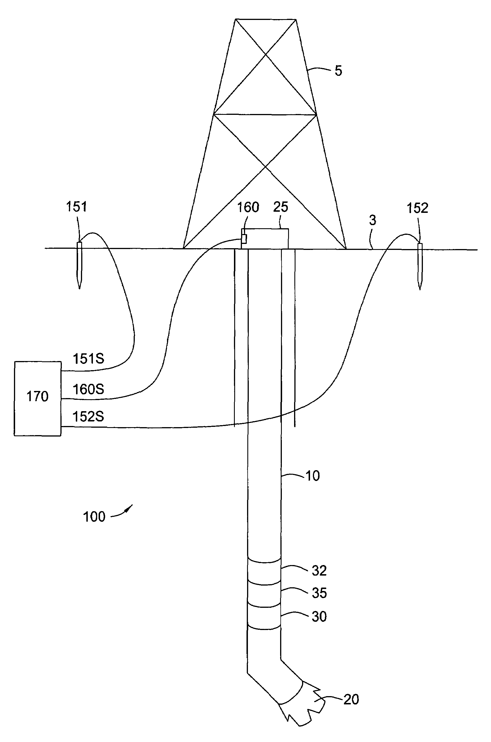
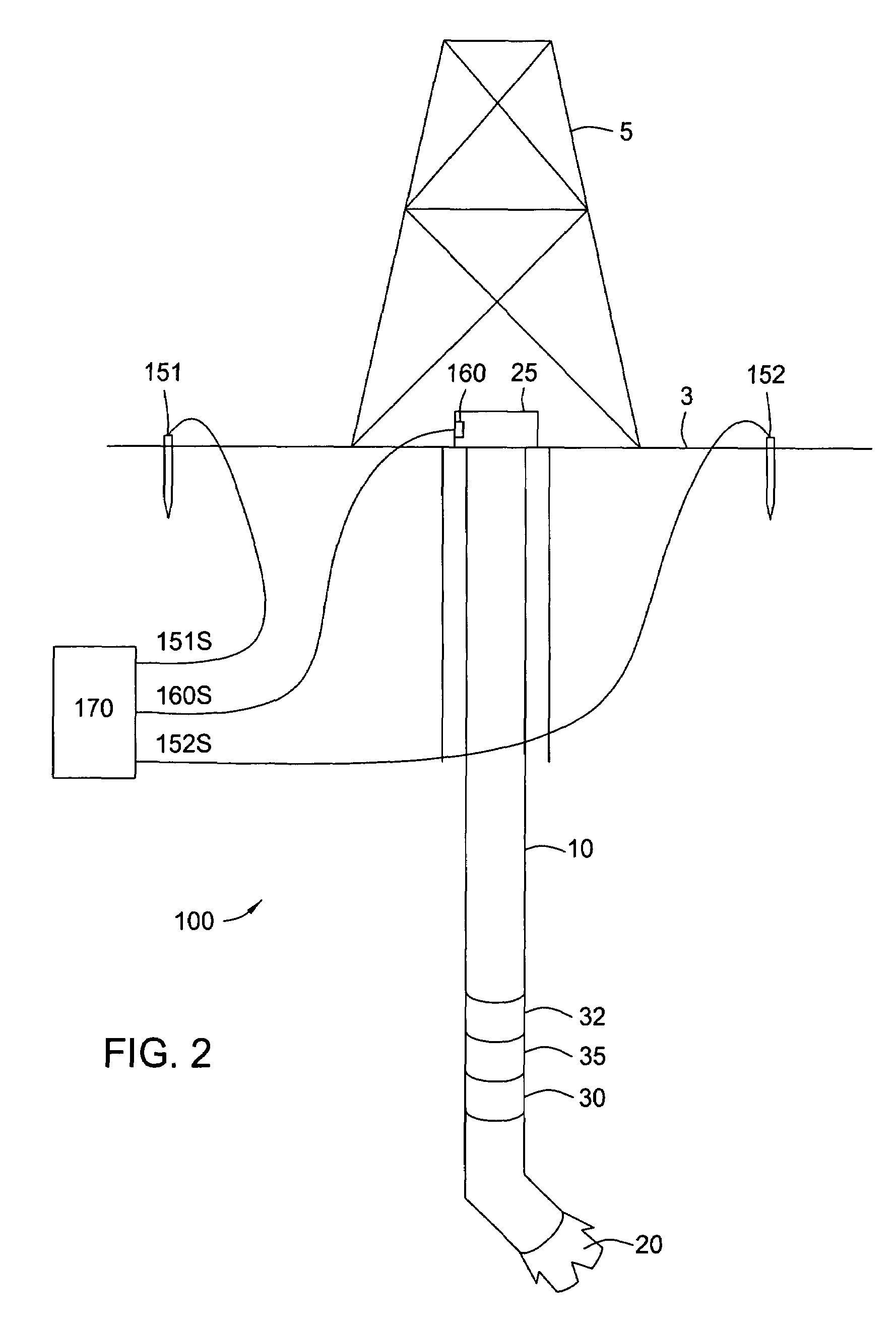
[0029]The present invention generally provides methods and apparatus for reducing noise in a detected electromagnetic wave used to telemeter data during a wellbore operation. In one embodiment, two surface antennae are placed on opposite sides of the wellbore and the same distance from the wellbore. The signals from the two antennae are summed to remove the noise from the signal transmitted from the EM downhole tool.

[0030]FIG. 2 illustrates an exemplary telemetry system 100 according to aspects of the present invention. The telemetry system 100 is employed to transmit data acquired during a drilling operation. In FIG. 2, a drill string 10 is shown with a drill bit 20 disposed at a lower end. The drill string 10 extends from a blow out preventer (“BOP”) 25 located at the surface 3. A rig 5 is positioned over the BOP 25 for raising and lowering the drill string 10. Although a drilling operation is shown, it is contemplated that aspects of the present invention are applicable to reduce...


PUM


Abstract

The present invention generally provides methods and apparatus for reducing noise in a detected electromagnetic wave used to telemeter data during a wellbore operation. In one embodiment, two surface antennae are placed on opposite sides of the wellbore and at the same distance from the wellbore. The signals from the two antennae are summed to reduce the noise in the electromagnetic signal transmitted from the electromagnetic downhole tool.

Description

CROSS-REFERENCE TO RELATED APPLICATIONS[0001]This application claims benefit of co-pending U.S. Provisional Patent Application Ser. No. 60 / 579,328, filed on Jun. 14, 2004, which application is herein incorporated by reference in its entirety.BACKGROUND OF THE INVENTION[0002]1. Field of the Invention[0003]Embodiments of the present invention generally relate to wireless data transmission systems. Particularly, the present invention relates to methods for increasing the reliability of detected electromagnetic waves. More particularly, the present invention relates to methods for reducing noise in a detected electromagnetic wave used to telemeter data from a drilling operation.[0004]2. Description of the Related Art[0005]Many operations in the drilling, evaluation, completion, and producing of oil and gas wells require communication between the surface of the earth and various devices located within the well borehole.[0006]During the drilling operation, various formation and drilling p...

Claims


Application Information

Patent Timeline
Patent Type & Authority Patents(United States)
IPC IPC(8): G01V1/28G01V11/00E21B44/00E21B47/12G01V1/22G01V3/34G08C25/00
CPCE21B47/12E21B47/122G01V11/002E21B47/13
Inventor YOUNG, ALLENNERO, MICHAELBARRY, LAURENCEHAWTHORNE, HUGHVILLARREAL, ROBERT
Owner WEATHERFORD TECH HLDG LLC
Why Eureka
Try Eureka