Cogeneration system

a cogeneration system and cogeneration technology, applied in the field of cogeneration systems, can solve the problems of limitation of conventional cogeneration systems in enhancing heating performance during heating operation, and achieve the effects of preventing compressor malfunction, maximizing absorption of engine waste heat, and increasing the condensing temperature of indoor heat exchangers

Inactive Publication Date: 2007-07-17
LG ELECTRONICS INC
View PDF9 Cites 11 Cited by
  • Summary
  • Abstract
  • Description
  • Claims
  • Application Information

AI Technical Summary

Benefits of technology

[0016]The present invention has been made in view of the above-mentioned problem, and it is an object of the invention to provide a cogeneration system in which waste heat generated from an engine is supplied to suction and discharge sides of a compressor, thereby achieving an enhancement in heating performance.
[0029]In the cogeneration system of the present invention, the suction side of the compressor absorbs the engine cooling water heat and secondary exhaust gas heat, and the discharge side of the compressor absorbs the primary exhaust gas heat. Accordingly, it is possible to maximize absorption of the waste heat of the engine while preventing compressor malfunction, and thus, to increase the refrigerant condensing temperature of the indoor heat exchanger. Thus, an enhancement in heating performance is achieved.

Problems solved by technology

However, since the waste heat generated from the gas engine 1 is used only to pre-heat the outdoor heat exchanger 25 through the air pre-heating heat exchanger 30, the conventional cogeneration system has a limitation in enhancing the heating performance during the heating operation.

Method used


Image

  • Cogeneration system
  • Cogeneration system
  • Cogeneration system

Examples


Embodiment Construction

[0035]Hereinafter, exemplary embodiments of a cogeneration system according to the present invention will be described with reference to the annexed drawings.

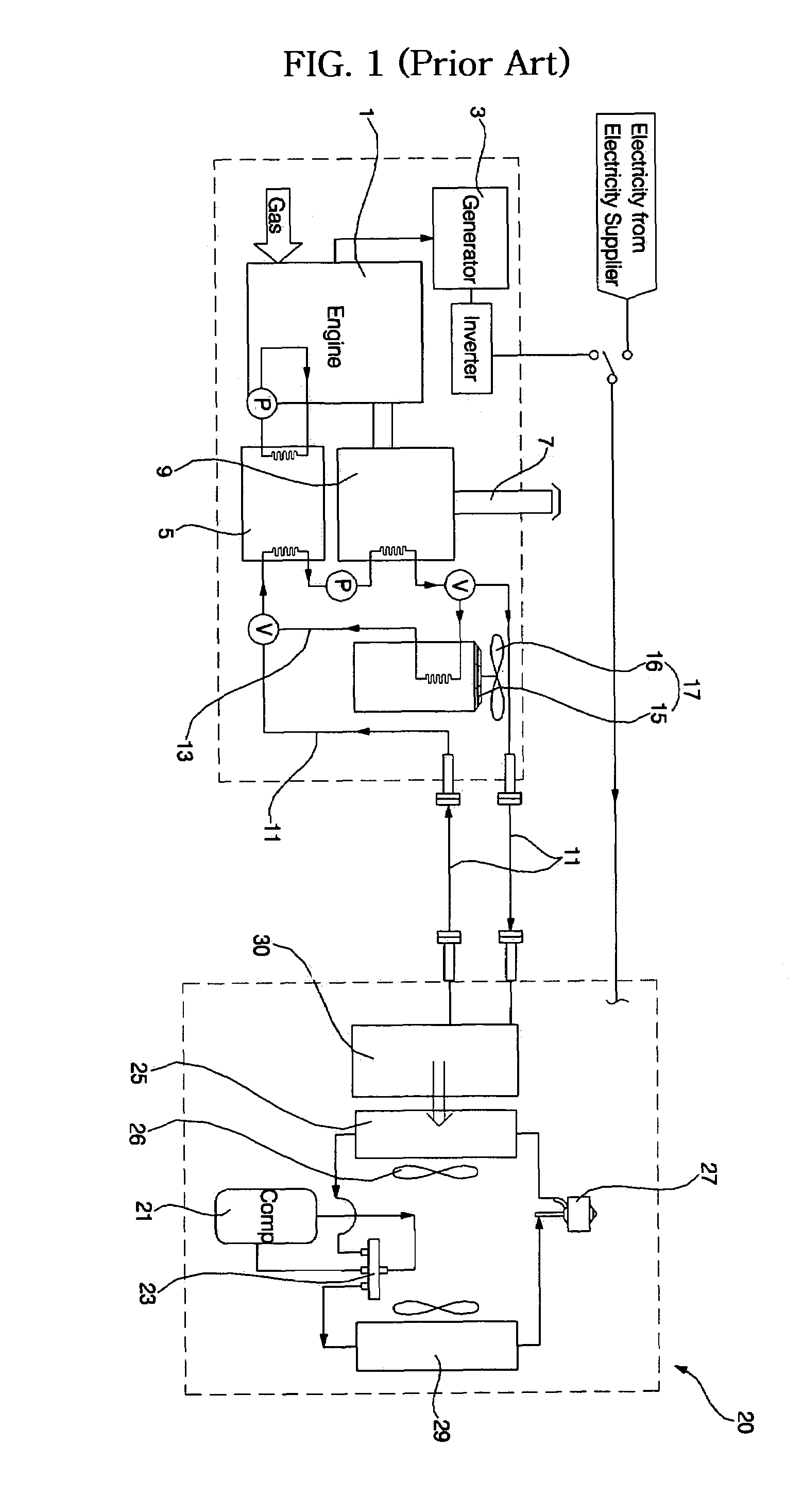
[0036]Although a number of embodiments may be implemented for the cogeneration system according to the present invention, the following description will be given in conjunction with the most preferable embodiment. Since the basic configuration of the cogeneration system is the same as that of the conventional cogeneration system, no detailed description thereof will be given.

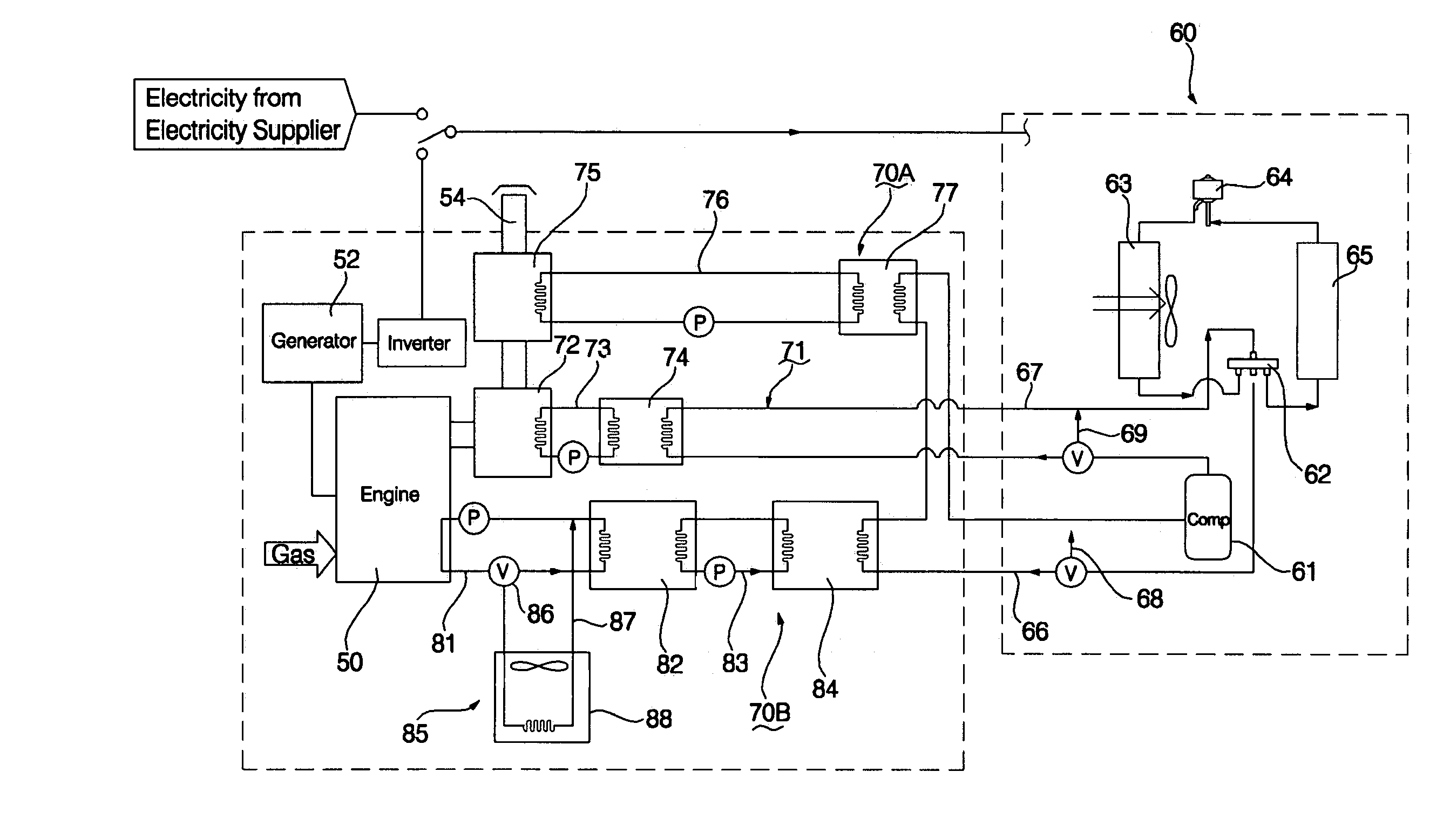
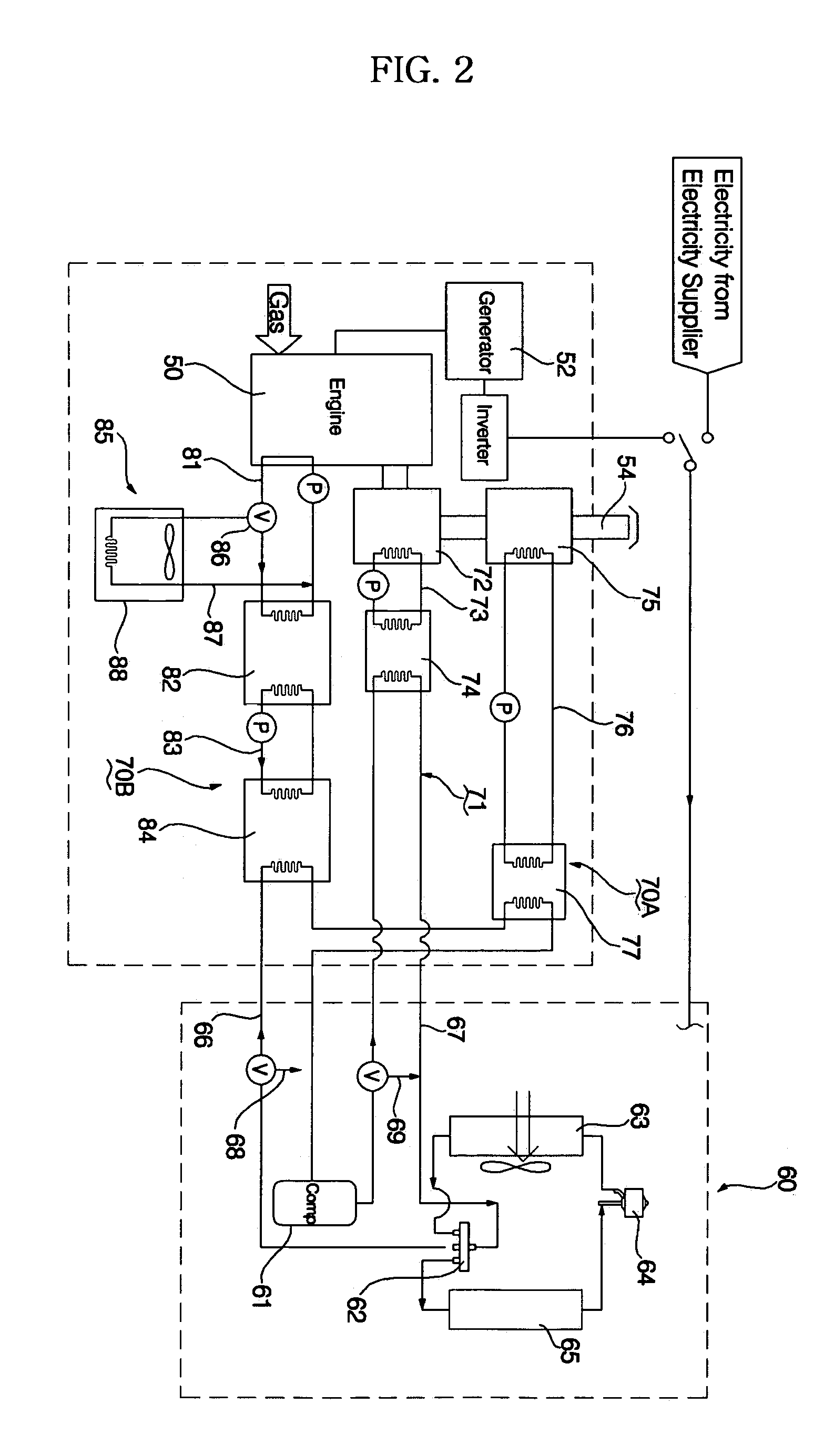
[0037]FIG. 2 is a schematic configuration diagram illustrating a cogeneration system according to an exemplary embodiment of the present invention.

[0038]As shown in FIG. 2, the cogeneration system includes an engine 50, which operates, using fossil fuel such as natural gas or petroleum gas, a generator 52 to generate electricity, using a driving force of the engine 50, first and second exhaust gas heat exchangers 72 and 75 arranged at an exhaust conduit 54 ...


PUM


Abstract

A cogeneration system including an engine, which drives a generator to generate electricity, a cooling / heating unit, which includes at least one compressor, a four-way valve, an outdoor heat exchanger, an expansion device, and an indoor heat exchanger, to establish a heat pump type refrigerant cycle, and a refrigerant over-heating unit to supply heat of cooling water used to cool the engine to a suction-side refrigerant line of the compressor of the cooling / heating unit, and to supply heat of exhaust gas discharged from the engine to the suction-side refrigerant line of the compressor and to a discharge-side refrigerant line of the compressor. In accordance with the cogeneration system, it is possible to maximize absorption of the waste heat of the engine while preventing compressor malfunction, and thus, to increase the refrigerant condensing temperature of the indoor heat exchanger. Thus, an enhancement in heating performance is achieved.

Description

BACKGROUND OF THE INVENTION[0001]1. Field of the Invention[0002]The present invention relates to a cogeneration system in which both the electricity and waste heat generated from an engine are used, and, more particularly, to a cogeneration system in which waste heat generated from an engine is supplied to suction and discharge sides of a compressor during a heating operation to achieve an enhancement in heating performance.[0003]2. Description of the Related Art[0004]In general, cogeneration systems are adapted to generate both electricity and heat from a single energy source.[0005]Such a cogeneration system can recover heat of exhaust gas or waste heat of cooling water generated from an engine or turbine during an electricity generation operation, so that the cogeneration system can achieve an increase in energy efficiency of 70 to 80% over other systems. By virtue of such an advantage, the cogeneration system has recently been highlighted as an electricity and heat supply source ...

Claims


Application Information

Patent Timeline
Patent Type & Authority Patents(United States)
IPC IPC(8): F25B27/02
CPCF25B13/00F25B27/00F25B2327/00F25B2400/06F25B2400/075F25B2500/02Y02E20/14Y02P80/15F02C6/18
Inventor CHO, EUN JUNRYU, YUN HOCHOI, YOUNG SEOBCHEONG, BAIK YOUNGLEE, JAE WON
Owner LG ELECTRONICS INC
Why Eureka
Try Eureka