Reduced carbon dioxide emission system and method for providing power for refrigerant compression and electrical power for a light hydrocarbon gas liquefaction process

a technology of light hydrocarbon gas and emission system, which is applied in the direction of gaseous fuels, machines/engines, light and heating apparatus, etc., can solve the problems of inability to construct pipelines to transport such natural gas, large energy consumption of most such processes, and inability to meet the requirements of liquefaction process requirements, so as to reduce carbon dioxide emission and reduce carbon dioxide emission

Active Publication Date: 2007-07-17
BP CORP NORTH AMERICA INC
View PDF18 Cites 8 Cited by
  • Summary
  • Abstract
  • Description
  • Claims
  • Application Information

AI Technical Summary

Benefits of technology

[0010]The present invention comprises a reduced carbon dioxide emission method for providing power for refrigerant compression and shared electrical power for a light hydrocarbon gas liquefaction process, the method comprising: a) compressing a refrigerant in a refrigerant compressor at least partially driven by at least one light hydrocarbon gas-fired turbine to produce the compressed refrigerant with the turbine producing an exhaust gas stream at an elevated temperature; b) producing steam at an elevated temperature and pressure from water or low-pressure steam by heat exchange with the exhaust gas stream; c) driving a steam turbine with the steam from b) to produce mechanical power; and d) driving an electrical power generator with the mechanical power from c) to produce electrical power for use in the light hydrocarbon gas liquefaction process.
[0011]The invention further comprises a reduced carbon dioxide emission system for providing power for refrigerant compression and s

Problems solved by technology

In many instances, it is not feasible to construct pipelines to transport such natural gas.
Most such processes are quite energy intensive and require substantial energy input to compress the refrigerant for repeated cycling through a refrigeration zone to produce the refrigeration necessary to at least partially liquefy the natural gas and the like.
Further, substantial energy may be required in many instances to recompress the

Method used


Image

  • Reduced carbon dioxide emission system and method for providing power for refrigerant compression and electrical power for a light hydrocarbon gas liquefaction process
  • Reduced carbon dioxide emission system and method for providing power for refrigerant compression and electrical power for a light hydrocarbon gas liquefaction process

Examples


Embodiment Construction

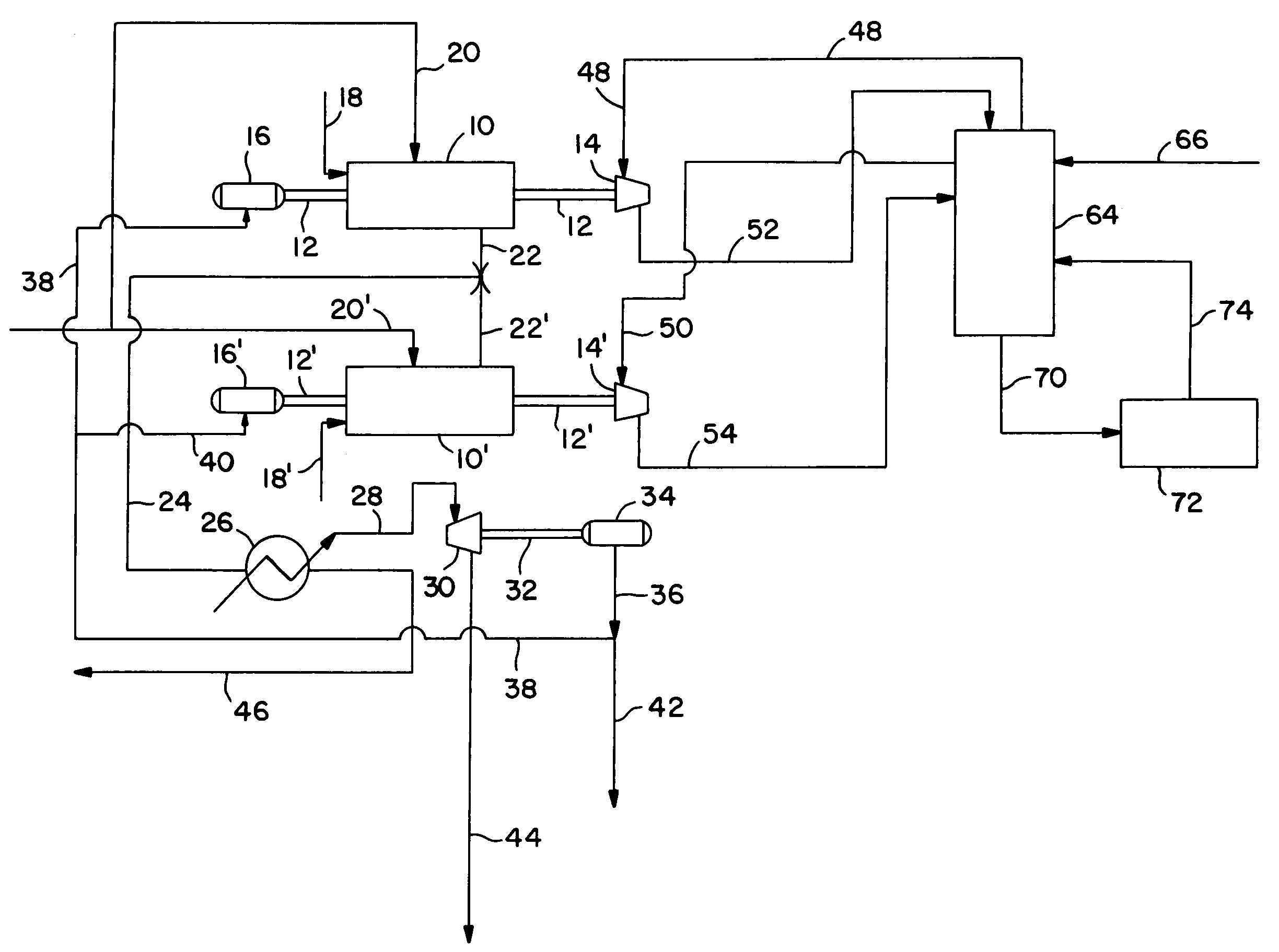
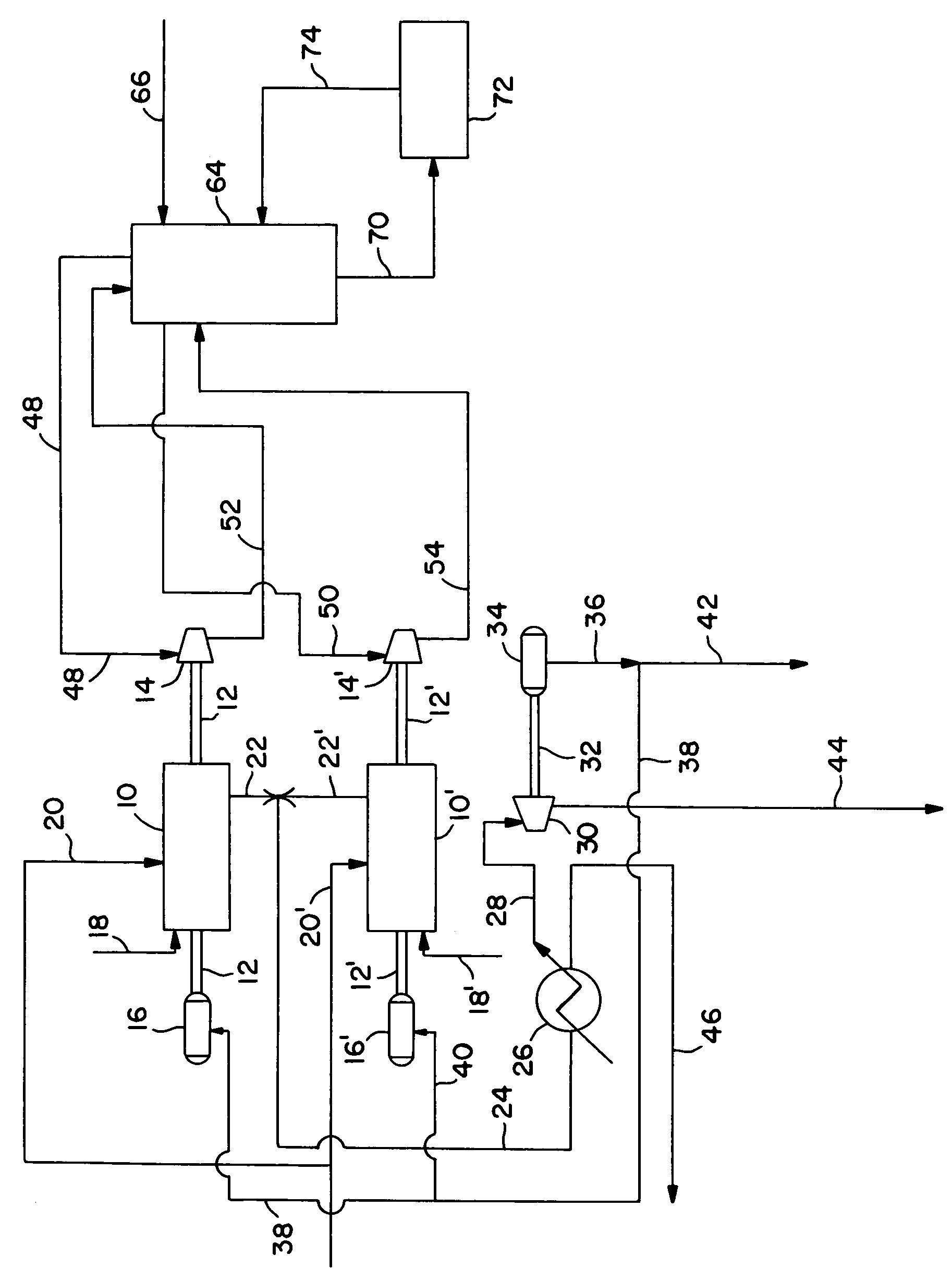
[0013]In the description of the FIGURE, the same numbers will be used throughout to refer to the same or similar components. It should be understood that many compressors, valves, motors and other equipment well known to the art and required to achieve the flows shown have not been shown for simplicity.

[0014]In the FIGURE, turbines 10 and 10′ are shown and are shaft coupled via shafts 12 and 12′ to compressors 14 and 14′. Compressors 14 and 14′ may be axial, centrifugal or the like compressors and are used to compress fresh or spent refrigerant from a natural gas liquefaction plant facility 64. The spent refrigerant is recovered from facility 64 through lines 48 and 50 and directed to turbines 14 and 14′ respectively. Alternatively, the spent refrigerant may be returned via a single line and passed to one or both turbines. The liquefied natural gas (LNG) is recovered via a line 70 and passed to storage in LNG storage and export facilities 72 from which a boil-off gas stream 74 is re...


PUM


Abstract

A reduced carbon dioxide emission system and method for providing power for refrigerant compression and shared electrical power for a light hydrocarbon gas liquefaction process.

Description

RELATED APPLICATIONS[0001]This application is entitled to and hereby claims the benefit of provisional application Ser. No. 60 / 414,806 filed Sep. 30, 2002.FIELD OF THE INVENTION[0002]This invention is related to a reduced carbon dioxide emission method for providing power for refrigerant compression and shared electrical power for a light hydrocarbon gas liquefaction process.[0003]The invention further comprises a reduced carbon dioxide emission system for producing power for refrigerant compression and shared electrical power for a light hydrocarbon gas liquefaction process[0004]Typically the light hydrocarbon gas is natural gas, which may have been treated to at least partially remove acid gases, dewatered, and from which at least a portion of the hydrocarbon gases heavier than about C3 may have been removed.BACKGROUND OF THE INVENTION[0005]In recent years, there has been continuing interest in liquefying natural gas and other light hydrocarbon gases at remote sites where there is...

Claims


Application Information

Patent Timeline
IPC IPC(8): F25J1/00F02C6/18C10L3/10F01D15/00F01K23/06F01K23/10F02C6/10F25J1/02
CPCC10L3/10C10L3/102F01D15/005F01K23/064F01K23/10F02C6/10F02C6/18F25J1/0022F25J1/027F25J1/0283F25J1/0287F25J1/0242F25J1/0274F25J2205/60F25J2220/64F25J2220/66F25J2240/70F25J2240/82Y02E20/16F05D2220/76F05D2220/72F05D2210/12
Inventor JONES, JR., RICHARDWARD, PATRICK B.
Owner BP CORP NORTH AMERICA INC
Why Eureka
Try Eureka