
Viscoelastic fluids containing nanotubes for oilfield uses

a technology of viscoelastic fluids and nanotubes, which is applied in the direction of sealing/packing, chemistry apparatus and processes, and well accessories, etc., can solve the problems of difficult handling or placement, low viscoelastic fluids use limit, and the use of micellar viscoelastic fluids for fracturing high permeability formations, etc., to achieve the effect of decreasing the viscosity of the fluid

Inactive Publication Date: 2007-07-17
SCHLUMBERGER TECH CORP
View PDF16 Cites 46 Cited by
  • Summary
  • Abstract
  • Description
  • Claims
  • Application Information

AI Technical Summary

Benefits of technology

This patent describes a new type of fluid that can be used in oil field applications, specifically fracturing fluids. This fluid contains nanotube structures made of carbon and other materials that can help improve the performance of the fluid in the formation. The fluid has a unique rheological behavior that makes it easier to pump and can help increase the production of oil and gas from the formation. The patent also describes a method for preparing the fluid by mixing carbon nanotubes into a viscoelastic fluid and sonicating it to incorporate the nanotubes. Overall, this patent presents a new and improved fluid for oil field applications that can help improve wellbore operations and increase oil and gas production.

Problems solved by technology

If the resulting viscosity of the viscoelastic gel is too high, handling or placement can become difficult.
Conversely, when viscosity is too low, other difficulties may be presented, for example, the viscoelastic gel may not transport other components or materials effectively.
Micellar viscoelastic fluids have limited use for fracturing high permeability formations.
In such environments, low concentrations of viscoelastic surfactants in fracturing fluids may not be sufficient to preclude fluid losses into the porous media of the high permeability formations due to low viscosity properties, thus requiring high concentrations of viscoelastic surfactant to maintain sufficient viscosity to limit fluid loss.
The result is a significant increase in cost and resource requirements for the operation.
Fluid lost to the formation may also problems with the function or technique of the fracture.
For example, the undesirable loss of fluid into the formation limits the fracture size and geometry that can be created during the fracturing pressure pumping operation.
Thus, the total volume of the fracture, or crack, is limited by the lost fluid volume that is lost into the rock, because such lost fluid is unavailable to apply volume and pressure to the rock face.

Method used


Image

  • Viscoelastic fluids containing nanotubes for oilfield uses
  • Viscoelastic fluids containing nanotubes for oilfield uses
  • Viscoelastic fluids containing nanotubes for oilfield uses

Examples


examples a

, B, and C

[0080]Using a 1 liter warring blender, 300 ml of the following viscoelastic surfactant fluid was prepared and then divided into three 100 ml portions.

[0081]

IngredientWeight %Propane-1,2-diol0.3%Propan-2-ol0.4%Water (aqueous medium)98.1%Eurycyl (Z)-13 Docosenyl-N-N-1.2%bis (2-Hydroxyethyl) MethylAmmonium Chloride

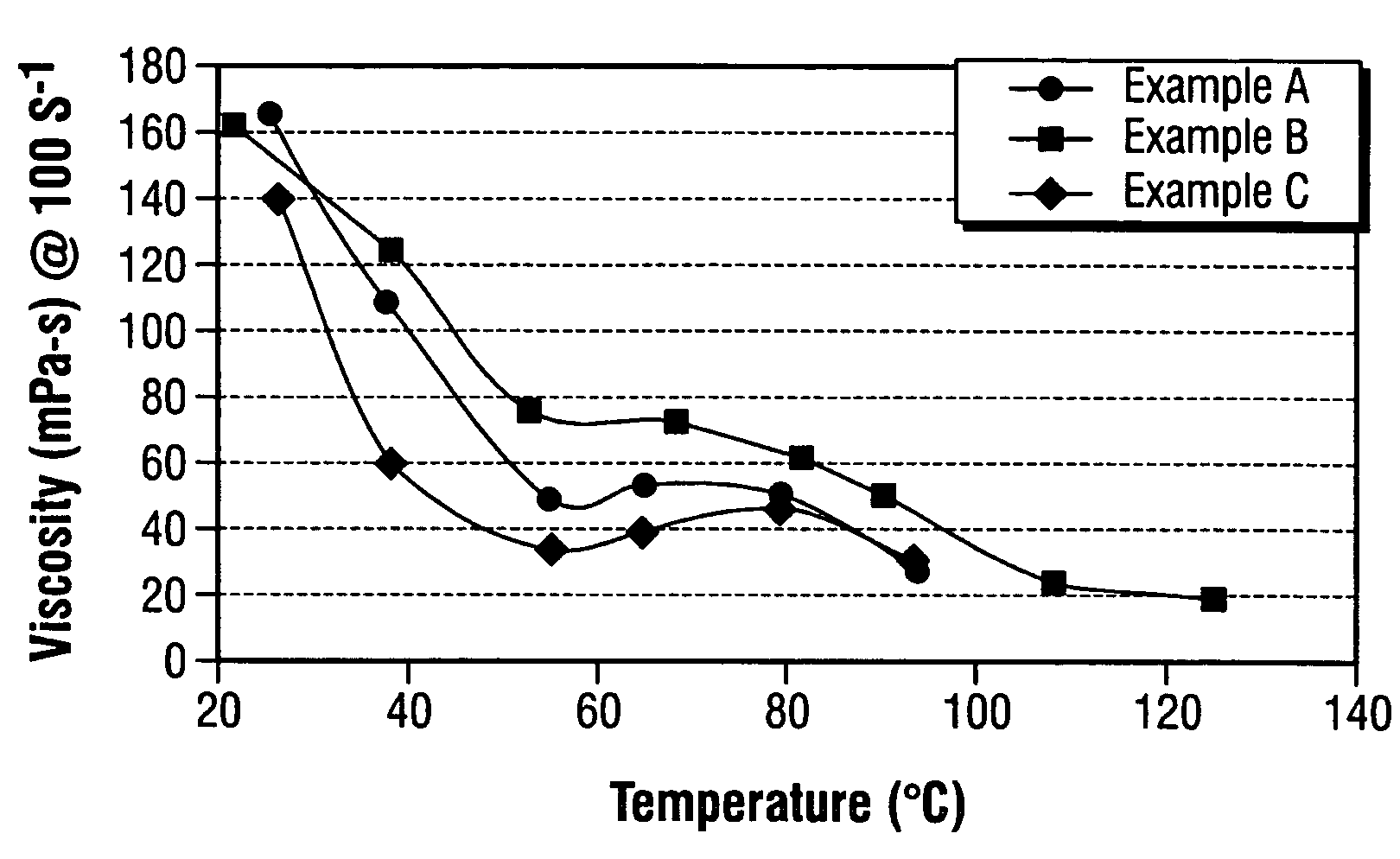
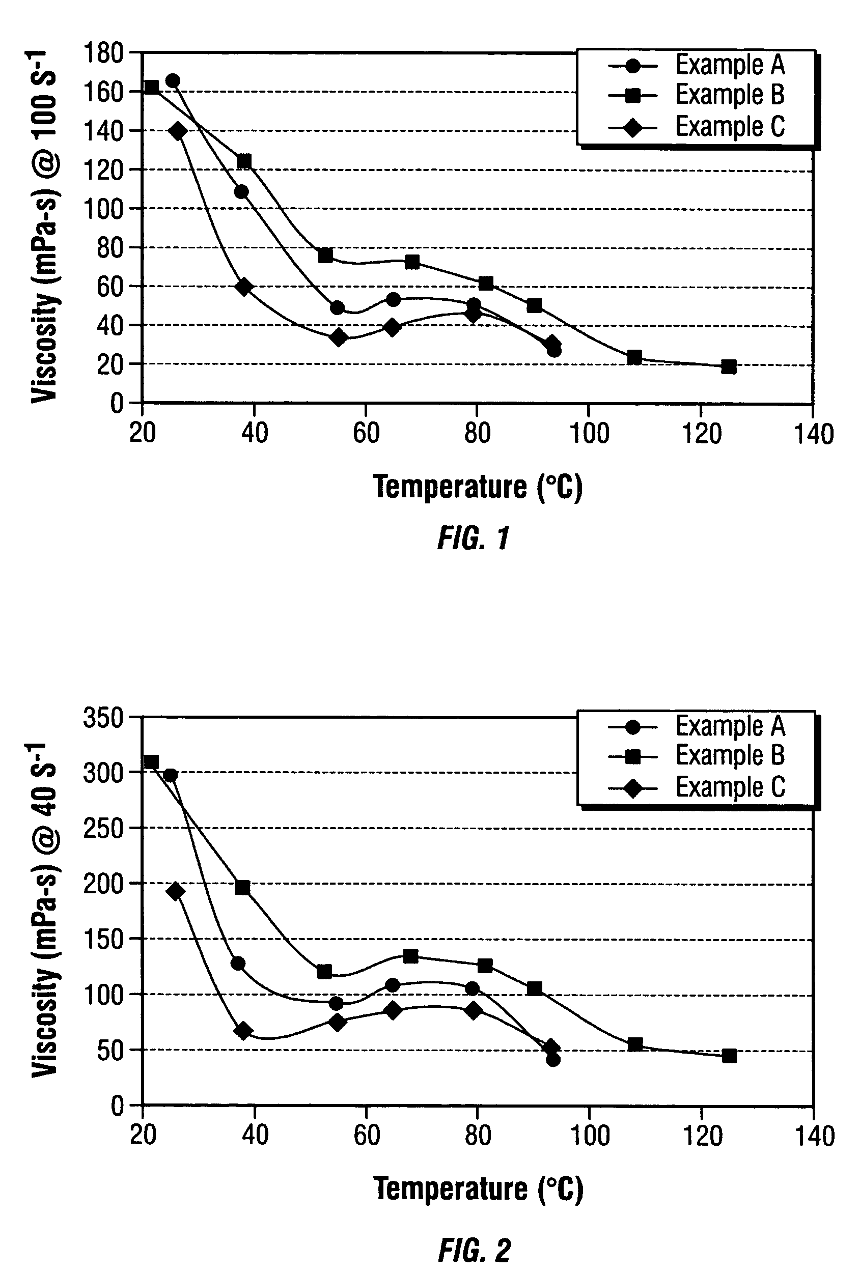
[0082]To a first 100 ml portion, 0.1% by weight single walled carbon nanotubes, available from Carbon Nanotechnologies Incorporated, was added to and blended for 2 minutes under low speed to prepare example A. To a second 100 ml portion, 0.2% by weight of the same carbon nanotube was added to and blended for 2 minutes under low speed to prepare example B. A third portion, was left untreated to form a control, example C. Then, mixtures underwent 80 minutes of sonication (all samples were sonicated for the same time to ensure that there is no artifact due to sonication). Then, 3% by weight of NH4Cl was added to all three examples, A, B and C. The viscosity was then me...

examples d and e

[0084]In a 1 liter warring blender, 200 ml of the following viscoelastic surfactant fluid was prepared and then divided into two 100 ml portions.

[0085]

IngredientWeight %Propane-1,2-diol0.3%Propan-2-ol0.4%Water (aqueous medium)98.1%Eurycyl (Z)-13 Docosenyl-N-N-1.2%bis (2-Hydroxyethyl) MethylAmmonium Chloride

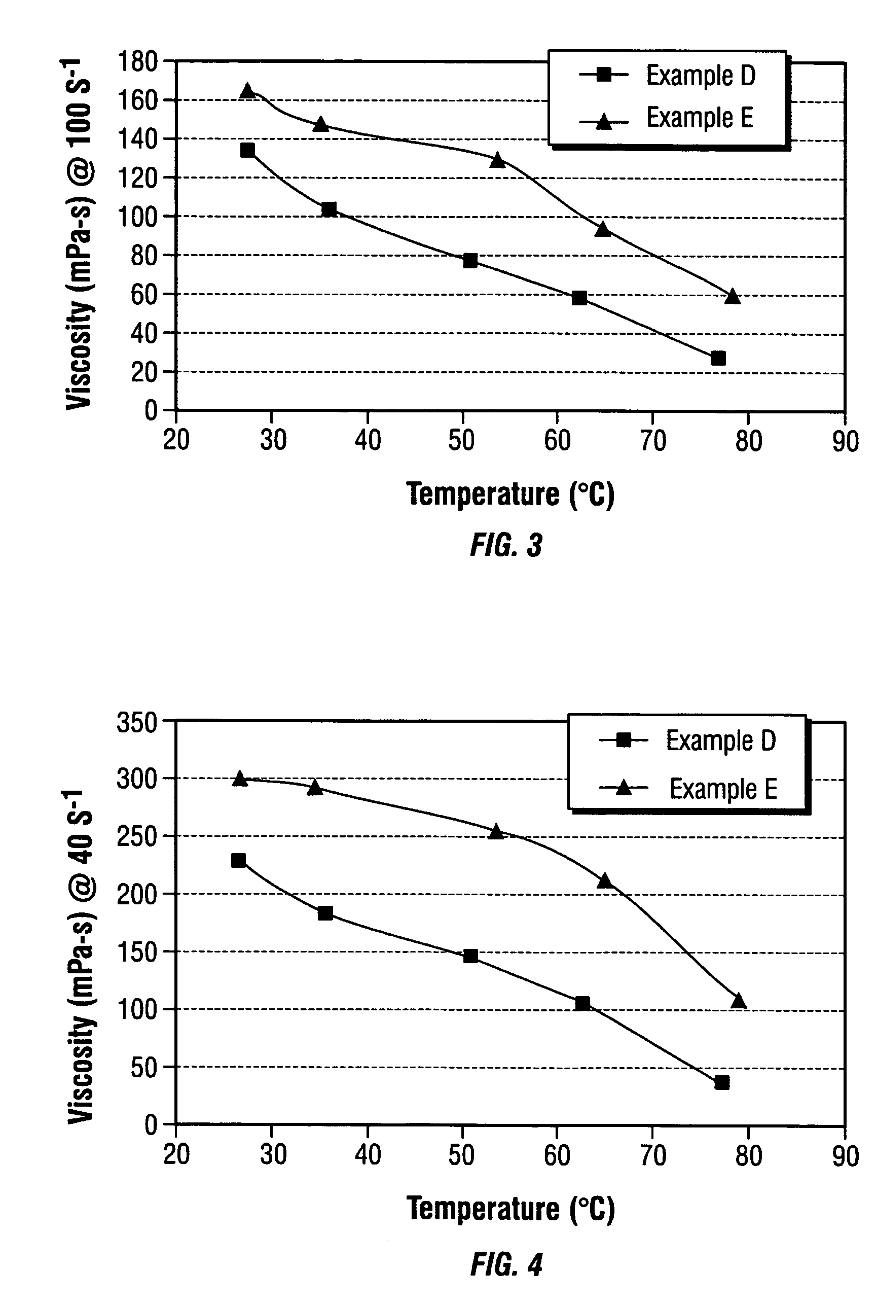
[0086]To a first 100 ml portion, 4% KCl was added to form example D. To a second 100 ml portion, 0.2% by weight single walled carbon nanotubes was added to and blended for 2 minutes under low speed, and then 4% KCl was added to prepare example E. Then, both mixtures underwent 80 minutes of sonication. The viscosity was then measured on a Fann 50 rheometer over several conditions.

[0087]FIG. 3 and FIG. 4 show the viscosity properties of viscoelastic surfactant fluid examples D and E as measured over a range of temperatures and at shear rates of 100 s−1 and 40 s−1. The data shows significant viscosity increase at like temperature when the carbon nanotubes are incorporated. Comparing ...

examples f

and G

[0088]To prepare samples F and G, 200 ml of the following viscoelastic surfactant fluid was prepared via warring blending and the separated into two 100 ml portions.

[0089]

IngredientWeight %Isopropanol0.5Sodium Chloride0.2Water48.3Erucic amidopropyl1.0dimethyl betainePropane-1,2-diol0.1Propan-2-ol0.1Water (aqueous medium)49.6Eurycyl (Z)-13 Docosenyl-N-N-0.2bis (2-Hydroxyethyl) MethylAmmonium Chloride

[0090]6% KCl was added to a first 100 ml portion in order to make example F. To a second 100 ml portion, 0.2% by weight single walled carbon nanotubes was added to and blended for 2 minutes under low speed, and then 6% KCl was added to prepare example G. Then, both mixtures underwent 80 minutes of sonication. The viscosity was then measured on a Fann 50 rheometer over several conditions.

[0091]FIG. 5 and FIG. 6 illustrate in graphic form, the viscosity properties of viscoelastic surfactant fluid examples F and G. The data shows significant viscosity increase with incorporated of carbo...


PUM

PropertyMeasurementUnit
temperaturesaaaaaaaaaa
static contact angleaaaaaaaaaa
diameteraaaaaaaaaa

Abstract

The present invention relates to viscoelastic fluids that contain nanotube structures that may be used advantageously as oilfield stimulation fluids in many different applications, most particularly as a fracturing fluid. Viscoelastic fluid compositions of the present invention include an aqueous medium, a viscoelastic surfactant, an organic or inorganic acids, or salt thereof, organic acid salts, inorganic salts, and a nanotube component. The invention is also called to a methods of treating a subterranean well bores in which the viscoelastic fluid is injected into the wellbore to perform operations such as fracturing, drilling, acid fracturing, gravel placement, removing scale, matrix acidizing, and removing mud cake. Further, a method of preparing a nanotube viscoelastic fluid comprising the steps of effectively mixing a carbon nanotube component into a viscoelastic fluid, and sonicating the mixture in order to incorporate the carbon nanotube component is claimed.

Description

BACKGROUND OF THE INVENTION[0001]1. Field of the Invention[0002]This invention relates to viscoelastic fluids, in particular, viscoelastic oilfield stimulation fluids containing nanotubes.[0003]2. Description of the Related Art[0004]Various types of oilfield stimulation fluids are used in operations related to the development, completion, and production of natural hydrocarbon reservoirs. These operations include fracturing subterranean formations, modifying the permeability of subterranean formations, or sand control. The oilfield stimulation fluids employed in these operations are known as drilling fluids, completion fluids, work over fluids, packer fluids, fracturing fluids, drilling fluids, conformance or permeability control fluids, and the like.[0005]Viscoelastic fluids are useful for carrying particles from one region of the formation, for instance, the wellbore or surface equipment, to another. As an example, one of the functions of a drilling fluid is to carry drilling cutti...

Claims


Application Information

Patent Timeline
Patent Type & Authority Patents(United States)
IPC IPC(8): C09K8/04C09K8/62
CPCB82Y30/00C09K8/03C09K8/52C09K8/602C09K8/68C09K8/74C09K2208/10C09K2208/30Y10S977/902Y10S507/922Y10S507/926
Inventor FU, DIANKUIDISMUKE, KEITHDAVIES, STEPHENWATTANA, ANN
Owner SCHLUMBERGER TECH CORP
Learn More