Encoding device for performing serial concatenated coding

a technology of concatenation coding and encoding device, which is applied in the direction of coding, error correction/detection using convolutional codes, and error correction/detection using turbo codes, etc., can solve the problem of the difference between the logical limit and the actual performance, and achieve the effect of improving the performance over the related ar

Inactive Publication Date: 2007-07-17
MITSUBISHI GAS CHEM CO INC +1
View PDF11 Cites 40 Cited by
  • Summary
  • Abstract
  • Description
  • Claims
  • Application Information

AI Technical Summary

Benefits of technology

[0034]The present invention has been made in view of the foregoing, and is intended to provide an encoding device, an encoding method, an encoding program, a decoding device, a decoding method, and a decoding program with improved performance over the related art.

Problems solved by technology

However, such SCCC and SCTCM systems have a problem in that there is a large difference between the logical limit and the actual performance, and therefore, there is still room for improvement in the performance.

Method used


Image

  • Encoding device for performing serial concatenated coding
  • Encoding device for performing serial concatenated coding
  • Encoding device for performing serial concatenated coding

Examples


first embodiment

(1-2) Operation of First Embodiment

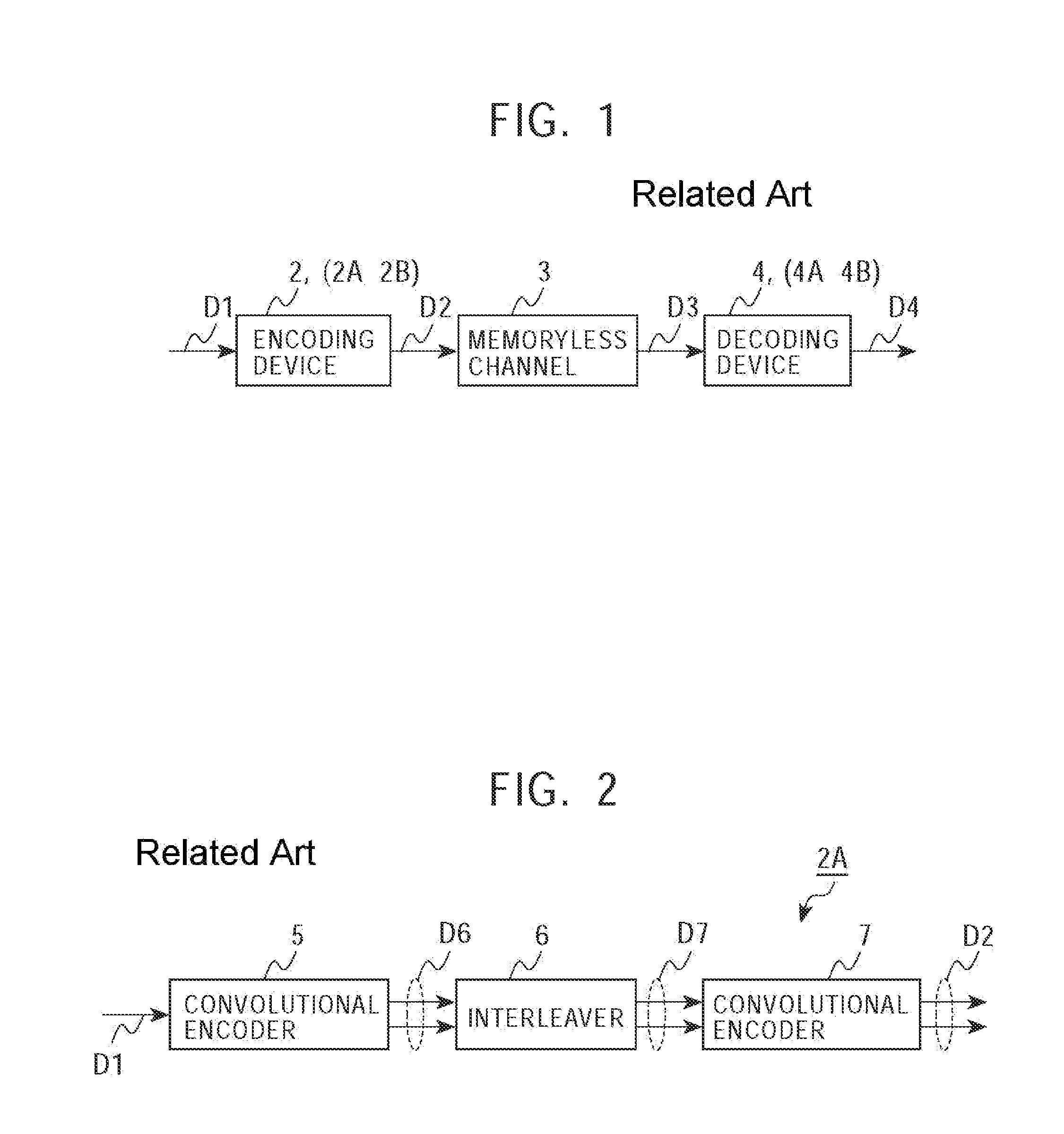
[0128]In the structure described above, in the data transmitting and receiving system 101 (see FIG. 14), the transmission data D101 is coded and 8PSK modulated by the encoding device 102 in the transmitter, and is then sent via the memoryless channel 103 to the receiver, in which the data D101 is decoded by the decoding device 104.

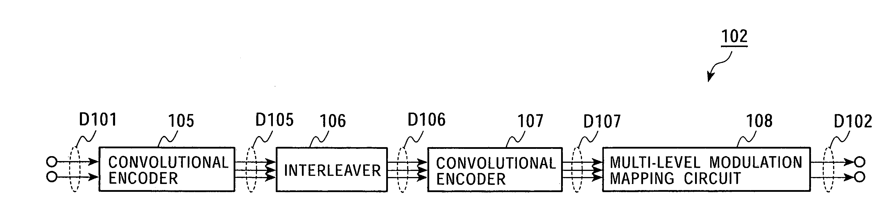
[0129]In the encoding device 102 (see FIG. 15), the data D102 is encoded with code rate 2 / 3 by the outer-code convolutional encoder 105, which serves as first encoding means, and is then permuted by the interleaver 106. The resulting data is encoded with code rate 3 / 3 by the inner-code convolutional encoder 107, which serves as second encoding means, and is then mapped by the multi-level modulation mapping circuit 108 onto a transmission symbol, which is then output.

[0130]In the data transmitting and receiving system 101, in this second encoding processing, two bit sequences out of three bit sequences are encoded so as to...

second embodiment

(2) Second Embodiment

[0148]FIG. 27 is a block diagram of an encoding device in a data transmitting and receiving system according to a second embodiment of the present invention. In the data transmitting and receiving system, an encoding device 202 performs serial concatenated convolutional coding on digital information D201 according to the SCOC scheme, and transmits the coded output D207 to a receiver via a noisy memoryless channel, and then a decoding device in the receiver decodes the transmitted output.

[0149]In the encoding device 202, the digital information D101 is convolutional coded with code rate k / p by an outer-code convolutional encoder 205, which serves as first encoding means, and the output data D205 is then interleaved by an interleaver 206. The resulting data is further convolutional coded with code rate p / n by an inner-code convolutional encoder 207, which serves as second encoding means, and is then output to the memoryless channel. Thus, finally, the encoding dev...


PUM


Abstract

The present invention is particularly applied to serial concatenated coding and serial concatenated trellis coded modulation. In second encoding 107, which is inner coding, a sequence that is not encoded or that is encoded so as to produce a finite impulse response and a sequence that is encoded so as to produce an infinite impulse response are output. In interleaving 106 before the second encoding 107, the sequences are permuted so as not to be mixed with each other.

Description

BACKGROUND OF THE INVENTION[0001]The present invention relates to an encoding device, an encoding method, an encoding program, a decoding device, a decoding method, and a decoding program. In particular, the present invention is applicable to serial concatenated coding and serial concatenated trellis coded modulation. In the present invention, in second coding, which is inner coding, a sequence that is not coded or that is coded so as to produce a finite impulse response and a sequence that is coded so as to produce an infinite impulse response are output, and, in interleaving before the second encoding, the sequences are permuted so as not to be mixed with each other, thus improving the performance over the related art.[0002]With the recent research and development in the communication field including mobile communications and deep space communications, the broadcasting field including terrestrial digital broadcasting and satellite digital broadcasting, recording and playback appar...

Claims


Application Information

Patent Timeline
Patent Type & Authority Patents(United States)
IPC IPC(8): H03M13/00G06F11/10H03M13/23H03M13/25H03M13/27H03M13/29H04L1/00
CPCH03M13/25H03M13/27H03M13/29H03M13/2972H04L1/0055H04L1/006H04L1/0065H04L1/0071H03M13/258H03M13/23
Inventor YOKOKAWA, TAKASHIMIYAUCHI, TOSHIYUKIIIDA, YASUHIROYAMAMOTO, KOHEIHATTORI, MASAYUKI
Owner MITSUBISHI GAS CHEM CO INC
Why Eureka
Try Eureka