Assembled camshaft for engine and production method thereof
- Summary
- Abstract
- Description
- Claims
- Application Information
AI Technical Summary
Benefits of technology
Problems solved by technology
Method used
Image
Examples
Embodiment Construction
[0032]There will be detailed below the preferred embodiments of the present invention with reference to the accompanying drawings. Like members are designated by like reference characters.
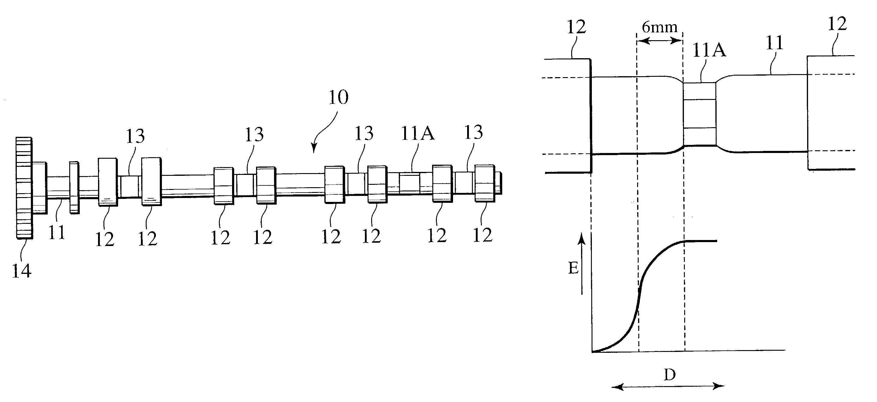
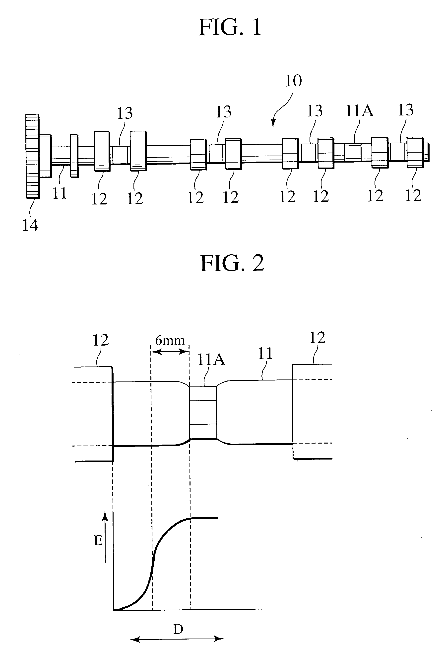
[0033]As shown in FIG. 1, an assembled camshaft 10 for engine according to an embodiment of the present invention has a hollow shaft member 11, a plurality of cam lobe pieces 12 and journals 13.
[0034]In addition, one end of the hollow shaft member 11 is fastened to a sprocket 14 which is driven to be rotated by a belt or a chain. The cam lobe piece 12 is, for example, a forging or a sinter, and it is located with a phase difference corresponding to a crank angle and is fitted into the hollow shaft member 11.
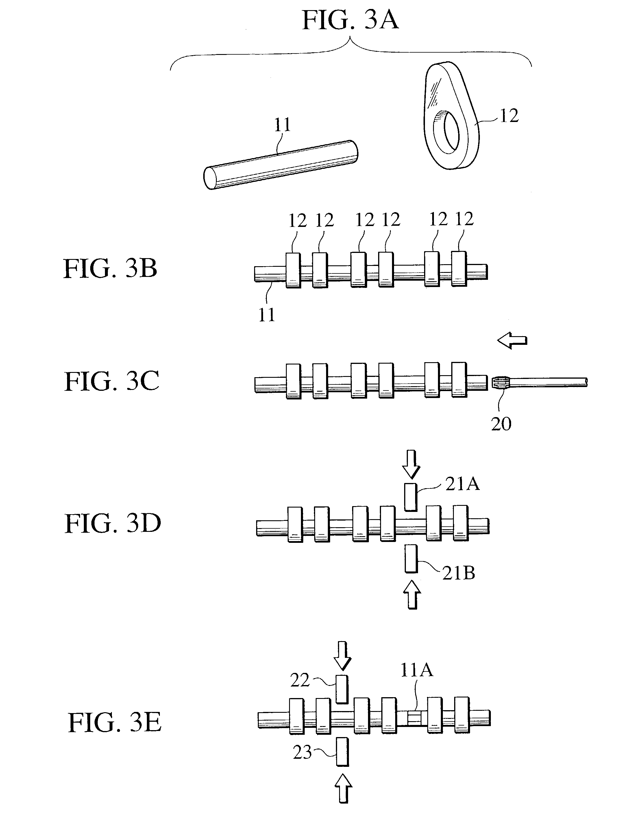
[0035]The hollow shaft member 11 has at least two shaft fixing surfaces 11A which are made of, for example, a steel pipe and are formed on a portion corresponding to a position between cylinders (or a position between the cam lobe pieces 12) by plasticity process. The shaft fixing surface 11A fu...
PUM
| Property | Measurement | Unit |
|---|---|---|
| Length | aaaaa | aaaaa |
| Current | aaaaa | aaaaa |
| Diameter | aaaaa | aaaaa |
Abstract
Description
Claims
Application Information
 - R&D
- Intellectual Property
- Life Sciences
- Materials
- Tech Scout
- Unparalleled Data Quality
- Higher Quality Content
- 60% Fewer Hallucinations
Browse by: Latest US Patents, China's latest patents, Technical Efficacy Thesaurus, Application Domain, Technology Topic, Popular Technical Reports.
© 2025 PatSnap. All rights reserved.Legal|Privacy policy|Modern Slavery Act Transparency Statement|Sitemap|About US| Contact US: help@patsnap.com


