Coolable segment for a turbomachine and combustion turbine

a turbomachine and combustion turbine technology, applied in machines/engines, liquid fuel engines, lighting and heating apparatus, etc., can solve the problems of reducing the overall efficiency of the combustion turbine, mechanical strength or lifetime reduction, etc., and achieve the effect of enhancing cooling features and segment cooling

Inactive Publication Date: 2007-07-24
SIEMENS AG
View PDF26 Cites 68 Cited by
  • Summary
  • Abstract
  • Description
  • Claims
  • Application Information

AI Technical Summary

Benefits of technology

[0013]It is an object of the invention to provide a coolable segment for a turbomachine to be exposed to a hot fluid with enhanced cooling features. It is a further object of the invention to provide a combustion turbine with an enhanced cooling of segments being exposed to a hot fluid which operates the combustion turbine.

Problems solved by technology

This leads on the one hand to the effect that either the segment has to withstand a higher temperature, which would lead to a reduction in mechanical strength or lifetime.
Using more cooling fluid, in particular cooling air, would lead to a reduced overall efficiency of the combustion turbine as the cooling air is normally separated from the air, which is fed to the combustor.

Method used


Image

  • Coolable segment for a turbomachine and combustion turbine
  • Coolable segment for a turbomachine and combustion turbine
  • Coolable segment for a turbomachine and combustion turbine

Examples


Embodiment Construction

[0050]In the drawing throughout the figures like reference numerals have the same meaning.

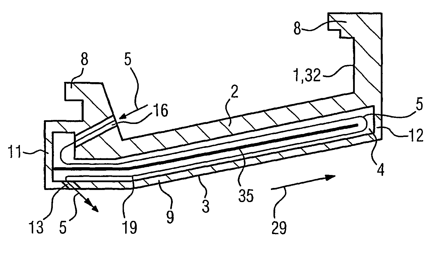
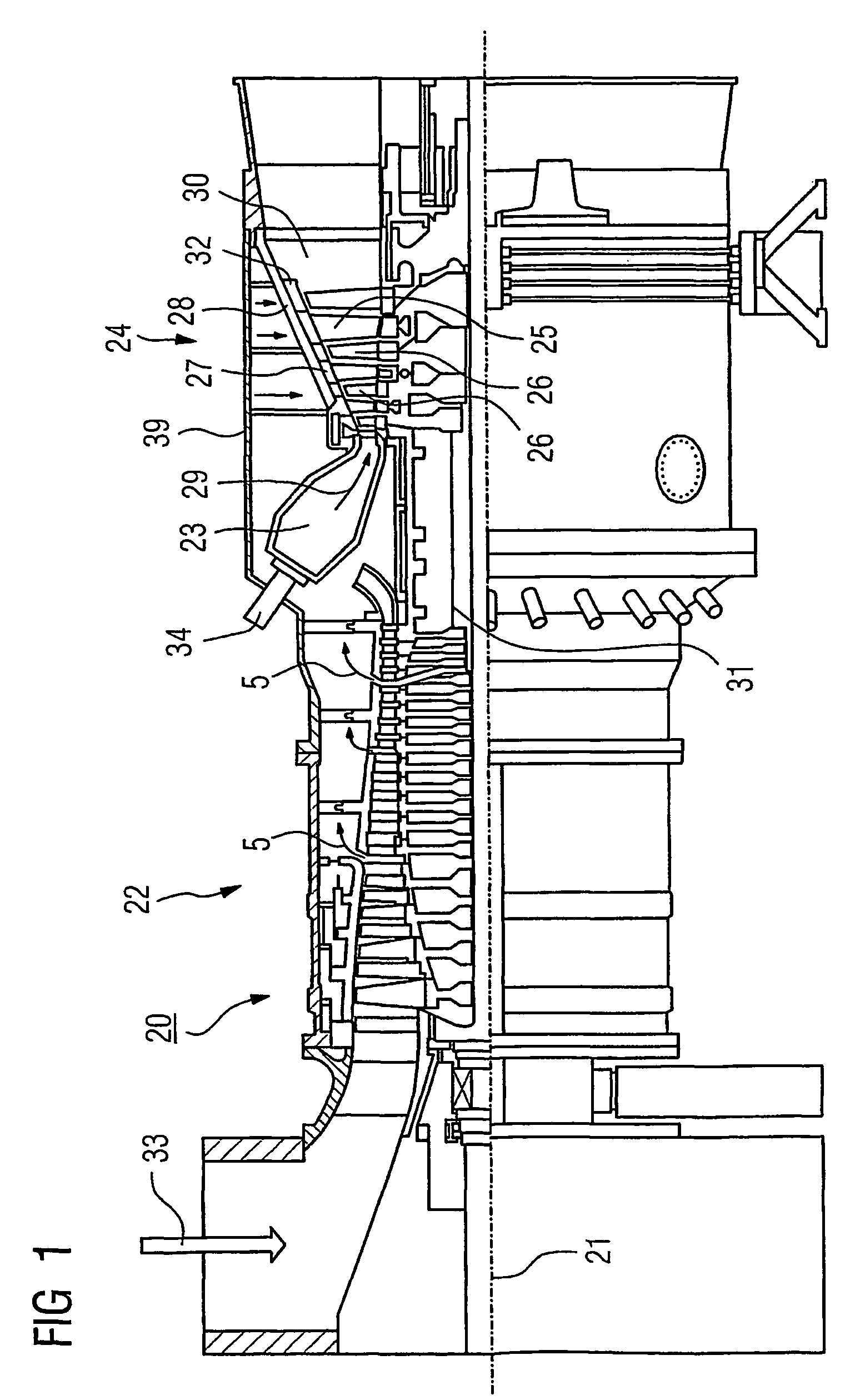
[0051]Referring now to the figures of the drawings in detail and first, in particular, to FIG. 1 thereof, there is shown in a cross-sectional view a stationary combustion turbine 20 as a turbomachinery extending along a main axis 21. The combustion turbine 20 comprises a compressor 22 for compressing air 33 which serves for the combustion process, a annular combustion chamber 23 having a number of burners 34 for a liquid or gaseous fuel and a turbine section 24, which turbine section 24 drives the compressor 22 and a not shown generator for generating electrical power. The combustion turbine 20 further comprises a turbine rotor 31 on which in the turbine section 24 four rows of rotating blades 26 being spaced apart along the main axis 21. The turbine section 24 further comprises an inner turbine housing 28 to which four rows of guide blades 25 (vanes) are attached in a circumferential direction...


PUM


Abstract

A coolable segment for a turbomachine such as a combustion turbine, which turbomachine is operated with a hot fluid. The segment comprises a cooling wall extending in an axial direction and in a circumferential direction orthogonal to the axial direction; a hot fluid surface to be exposed to the hot fluid. Between the wall and the surface a cooling structure is arranged which is permeable to cooling fluid and provides cooling surfaces for cooling by heat transmission through radiation. The cooling structure comprises either a netting, in particular a wire netting or a porous material.

Description

CROSS REFERENCE TO RELATED APPLICATIONS[0001]This application is a continuation of International Application No. PCT / EP02 / 07029, filed Jun. 25, 2002 and claims the benefit thereof. The International Application claims the benefits of British application No. 0117110.7 filed Jul. 13, 2001, both of the applications are incorporated by reference herein in their entirety.BACKGROUND OF THE INVENTION[0002]Field of the Invention[0003]The invention relates to a coolable segment of a turbomachinery, in particular a shroud or guide blade plate (guide ring segment) of a combustion turbine. The invention also relates to a combustion turbine having a coolable segment.[0004]An important consideration in the design of a turbomachine, in particular gas turbine engines or steam turbines, is to ensure that various components of the engine are maintained at safe operating temperatures. This is particularly true for elements of a gas turbine like a combustor and a turbine section, which are exposed to t...

Claims


Application Information

Patent Timeline
Patent Type & Authority Patents(United States)
IPC IPC(8): F01D25/12F01D11/08F01D5/28F01D25/14F01D25/24F02C7/00F02C7/18F02K1/82F23R3/00F23R3/06
CPCF01D25/12F01D25/14F02K1/822F23R3/005F23R3/007F23R3/06F23R2900/03041Y02T50/67Y02T50/676F05D2260/20Y02T50/60
Inventor BOLMS, HANS-THOMASHESELHAUS, ANDREASHOFFSCHMIDT, BERNHARD
Owner SIEMENS AG
Why Eureka
Try Eureka