Radio frequency power amplifier module

a power amplifier and module technology, applied in the direction of amplifiers with min 3 electrodes or 2 pn junctions, gain control, transmission, etc., can solve the problems of increased chip price, limited degree of freedom of mounting other components, and inability to obtain sufficient inductance valu

Inactive Publication Date: 2007-07-24
RENESAS ELECTRONICS CORP
View PDF14 Cites 8 Cited by
  • Summary
  • Abstract
  • Description
  • Claims
  • Application Information

AI Technical Summary

Benefits of technology

[0013]The aforementioned problem of the present invention can be dissolved effectively by using at least a bonding pad having a capacitance component to a ground and a bonding wire formed via the bonding pad in the bias supply line that connects the bias control part and the radio frequency power amplifier part.

Problems solved by technology

In such circumstances, when the inductance chip components described in the Background of the Invention are used as the inductors 908 and 909, a problem is arisen that a degree of freedom of mounting other components is limited due to loading of relatively large inductance chip components on the module substrate the downsizing of which is advancing.
As a result, a problem is arisen that a bias voltage drop occurs, then semiconductor area increases to cause an increased chip price.
Accordingly, a sufficient inductance value is not obtained and the attenuation of a radio frequency signal is inevitably insufficient.

Method used


Image

  • Radio frequency power amplifier module
  • Radio frequency power amplifier module
  • Radio frequency power amplifier module

Examples


Embodiment Construction

[0026]A radio frequency power amplifier module according to the present invention is described below with reference to the embodiments of the invention shown in the drawings. Identical symbols in FIGS. 1, 2, 5 to 7, 9 and 10 show identical or similar articles.

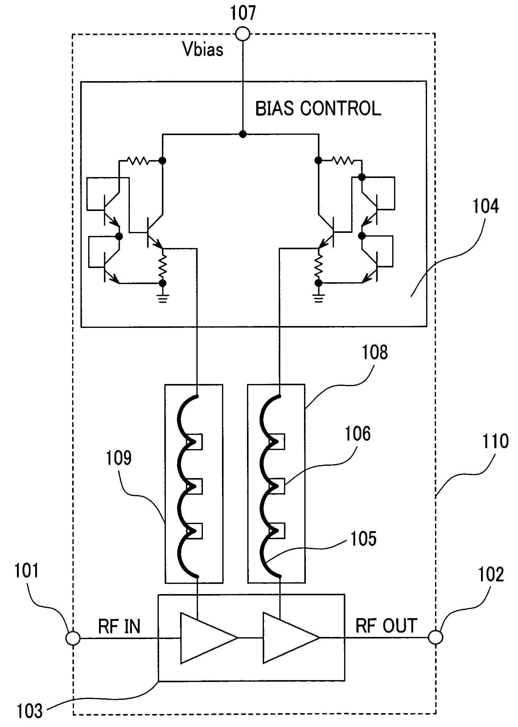
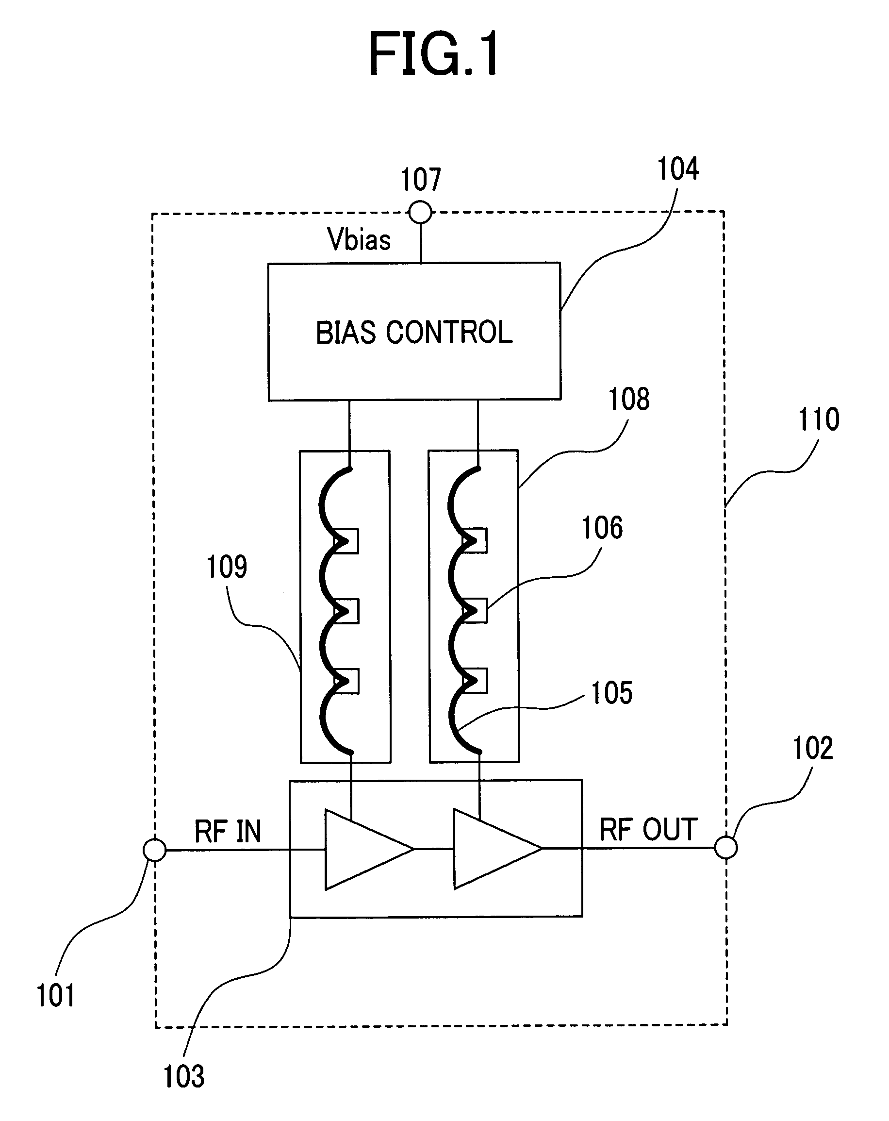
[0027]FIG. 1 shows an embodiment in which a radio frequency power amplifier part of 2-stage amplification is mounted in a module substrate. In FIG. 1, 110 denotes a module substrate, 103 the radio frequency power amplifier part of 2-stage amplification that performs amplification via the first stage and the final stage, 104 a bias control part that supplies the radio frequency power amplifier part 103 with a direct current bias, and 108 or 109 a bias supply line that connects the bias control part 104 and the radio frequency power amplifier part 103, respectively. A radio frequency power amplifier module is constituted by mounting the aforementioned parts in the module substrate 110. The radio frequency power amplifier part 103...


PUM


Abstract

A radio frequency power amplifier module that brings sufficient attenuation to a radio frequency signal in a bias supply line connecting a bias control part and a radio frequency power amplifier part without increasing module substrate area is aimed. At least one bonding pad 106 having a capacitance component to a ground and stitch structure inductances 108, 109 composed of a bonding wire 105 provided via the bonding pad are provided in the bias supply line connecting the bias control part and the radio frequency power amplifier part.

Description

CLAIM OF PRIORITY[0001]The present patent application claims priority from Japanese application JP 2003-118030 filed on Apr. 23, 2003, the content of which is hereby incorporated by reference into this application.FIELD OF THE INVENTION[0002]The present invention relates to a radio frequency power amplifier used in the transmitting part of a radio communications apparatus, such as a cellular phone, and, more particularly to a radio frequency power amplifier module having a bias control circuit.BACKGROUND OF THE INVENTION[0003]A radio frequency power amplifier used in a radio communications apparatus, such as a cellular phone, in a mobile communications system is classified roughly into a radio frequency power amplifier part that amplifies a radio frequency power and a bias control part that supplies the radio frequency power amplifier part with a direct current voltage. Further, usually, the power amplifier mounts these parts in a module substrate and is constituted as a radio frequ...

Claims


Application Information

Patent Timeline
Patent Type & Authority Patents(United States)
IPC IPC(8): H03G3/10H03F3/24H03F1/02H03F1/30H03F3/195H04B1/04
CPCH03F1/02H03F1/30H03F3/195H01L2224/73265
Inventor OHNISHI, MASAMITANOUE, TOMONORIMATSUMOTO, HIDETOSHI
Owner RENESAS ELECTRONICS CORP
Why Eureka
Try Eureka