Compensation of I-Q imbalance in digital transceivers

a digital transceiver and imbalance technology, applied in the field of digital transceivers, can solve problems such as imbalances in transmitter and receiver, inability to generate perfect complex sinusoids using analog circuits, and problems such as in-band image folding,

Active Publication Date: 2007-07-24
MICROCHIP TECH INC
View PDF35 Cites 97 Cited by
  • Summary
  • Abstract
  • Description
  • Claims
  • Application Information

AI Technical Summary

Benefits of technology

[0029]Embodiments of the present invention may be employed with various transceiver architectures, including, but not limited to, direct conversion, high IF and low IF super-heterodyne, and wideband IF (also known as indirect zero-IF) architectures. Moreover, embodiments of the invention may be easily employed in various communication modes, such as, but not limited to, time-division duplex (TDD) systems and frequency-division duplexed (FDD) systems.
[0030]Embodiments of the present invention provide a complete solution to compensate for both receiver as well as transmitter imbalance and enables calibration in local radio units as well as real-time compensation over-the-air during normal operation, or a combination of both.

Problems solved by technology

Folding of image in-band is a problem especially if the value of ωi−ω0 is small.
In practice, it is not possible to generate a perfect complex sinusoid using analog circuits due to process variation and asymmetry in layouts.
It is apparent that an unwanted signal
I-Q imbalances introduce distortions in the transmitter and receiver.
Imbalances are the result of asymmetry in circuit layouts and non-uniformity in IC fabrication processes (such as threshold mismatch and device mismatches).
Typical RF transceivers operating at a few GHz may achieve 2 degrees and 2% of phase and amplitude mismatches even with careful layouts.
While the mismatches seem small, they introduce additional distortions in RF systems so that bit-error rate is increased.
Also, the mismatches worsen for higher carrier frequencies, for example millimeter wave.
I-Q imbalance is especially detrimental to high-performance RF systems that use high-order modulations.

Method used


Image

  • Compensation of I-Q imbalance in digital transceivers
  • Compensation of I-Q imbalance in digital transceivers
  • Compensation of I-Q imbalance in digital transceivers

Examples


Embodiment Construction

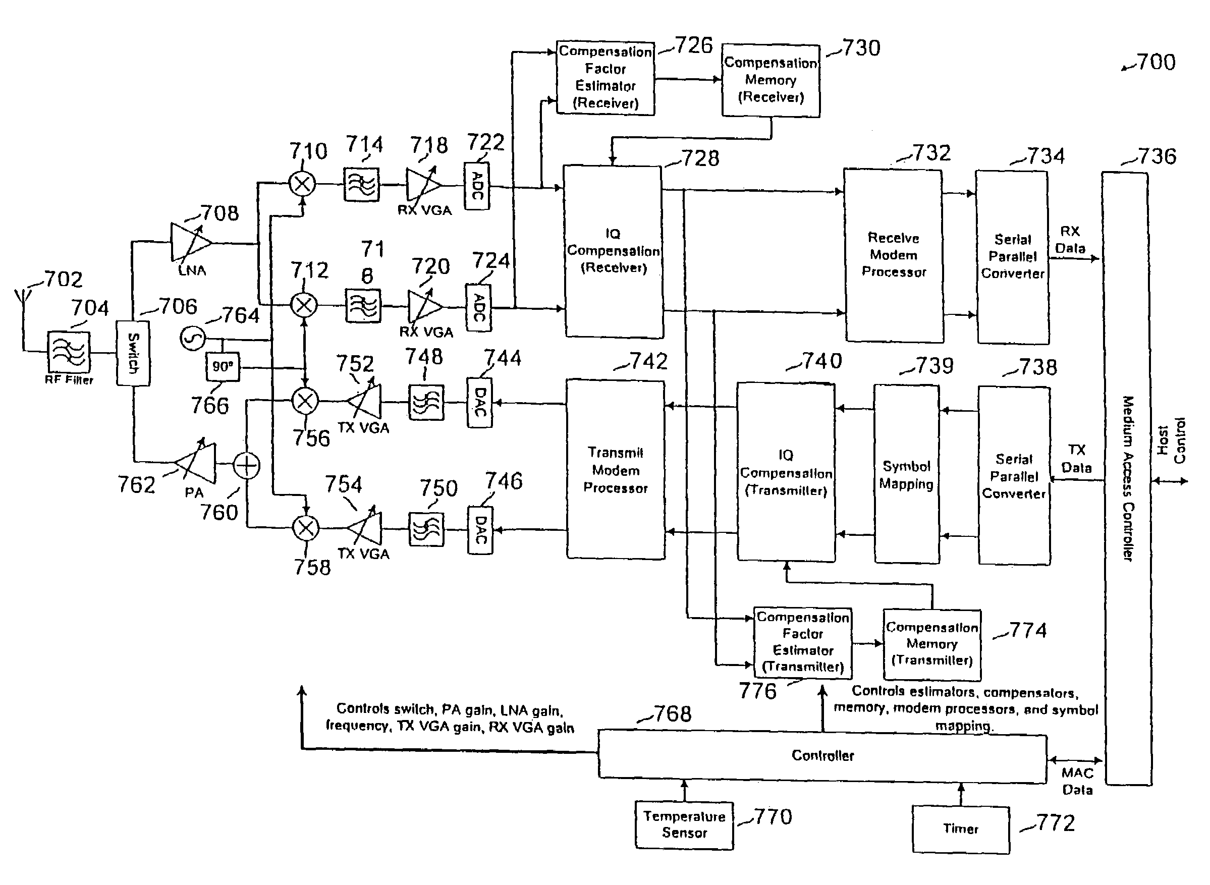
[0083]Embodiments of the present invention reduce I-Q imbalances through compensation using systems and methods that may be implemented with low-complexity and low-cost using existing IC technologies. Moreover, because the present invention lends well to a digital implementation, it may be easily integrated with the existing digital processing that occurs in a RF radio system in one of several possible ways. Non-limiting examples of possible implementations of embodiments of the present invention are shown in FIGS. 6A, 6B and 6C. A two chip solution is shown in FIG. 6A where the compensation is part of a mixed-signal chip that interfaces to the RF with analog-to-digital converters (ADC) and digital-to-analog converters (DAC). The digital function performs modem and medium access (MAC) processing. Another approach is shown in FIG. 6B where the compensation is part of the RF front-end with a general programmable digital interface bus, that may be serial, parallel, or a mixture of both...


PUM


Abstract

A transceiver includes a switching unit configurable for isolating an input of a receiver from an output of a transmitter during a local calibration mode. A known signal present at the output at a first power level during the calibration mode will also be present at the input at a second power level lower than the first power level and will be converted by the quadrature demodulator. A compensation factor is estimated for compensating the receiver section for imbalances in the in-phase and quadrature phase signals resulting from conversion of the known signal. Remote calibration is implemented using a method for remotely compensating for I-Q imbalance wherein a data packet having a known signal is transmitted to a receiver for conversion by a quadrature demodulator and compensation factors are estimated for compensating for imbalances in the in-phase and quadrature phase signals resulting from conversion of the known signal.

Description

BACKGROUND OF THE INVENTION[0001]1. Field of the Invention[0002]Embodiments of the present invention relate to digital transceivers for use in communication systems, and in preferred embodiments, to systems and methods for providing compensation for I-Q imbalance in digital transceivers.[0003]2. Description of Related Art[0004]In communication systems, quadrature up and down-conversion are needed to perform frequency translations. In general, the transmitter uses a quadrature up converter to convert a signal to a higher frequency while the receiver uses a quadrature down converter to convert a signal to a lower frequency. An example of a quadrature converter 102 is shown in FIG. 1., Quadrature converter 102 includes two mixers 104, 106 and an oscillator 108. The paths that are associated with the x and y inputs to mixers 104 and 106, respectively, are referred to as the I-channel and Q-channel. The oscillator 108 provides a cosω0t signal input to mixer 104 and a ksinω0t signal input...

Claims


Application Information

Patent Timeline
Patent Type & Authority Patents(United States)
IPC IPC(8): H04B1/38H04B1/00H04B17/00H04B1/30H04L27/00
CPCH04B1/30H04L27/0014H04B17/20H04L2027/0024H04L2027/0016
Inventor CHIEN, CHARLES
Owner MICROCHIP TECH INC
Why Eureka
Try Eureka