Fuel injection apparatus for internal combustion engine

a fuel injection apparatus and internal combustion engine technology, which is applied in mechanical equipment, liquid fuel feeders, machines/engines, etc., can solve the problems of increasing the cost of the system, increasing the pressure of the fuel injection system, and approaching the limit of pressure intensification in the fuel injection system of a diesel engine mounted in a vehicle such as an automobile, so as to prevent the pressure fluctuation and the effect of inexpensive structur

Inactive Publication Date: 2007-07-31
DENSO CORP
View PDF14 Cites 9 Cited by
  • Summary
  • Abstract
  • Description
  • Claims
  • Application Information

AI Technical Summary

Benefits of technology

[0013]An object of the present invention is to provide a fuel injection apparatus for an internal combustion engine that has an inexpensive structure but can protect a solenoid valve from the pressure fluctuation of return fuel flowing out of a pressure intensifier or a fuel injection nozzle. Moreover, the object of the present invention is to provide a fuel injection apparatus for an internal combustion engine that can protect a solenoid valve from the pressure fluctuation of return fuel in a return pipe for merging the flow of return fuel flowing out of a pressure intensifier or a fuel injection nozzle with the flow of return fuel flowing out of a solenoid valve to return the flow of return fuel collectively to the low pressure side of a fuel system.
[0015]With this, the flow of return fuel flowing out of the pressure intensifier or the fuel injection nozzle is returned directly to the low-pressure side of the fuel system without being merged with return fuel flowing out of the solenoid valve. That is, there is provided a channel structure (pipe line structure) that is not provided with a merging portion where the flow of return fuel flowing out of the pressure intensifier or the fuel injection nozzle merges with the flow of fuel flowing out of the solenoid valve. Hence, this channel structure can prevent the pressure fluctuation of return fuel flowing out of the pressure intensifier or the fuel injection nozzle from propagating to the solenoid valve. Therefore, the fuel injection apparatus according to the present invention has an inexpensive structure but can protect the solenoid valve from the pressure fluctuation of return fuel flowing out of the pressure intensifier or the fuel injection nozzle.

Problems solved by technology

However, pressure intensified in the fuel injection system for a diesel engine mounted in a vehicle such as an automobile is approaching a limit.
For example, also in a common rail type fuel injection system, a request to intensify injection pressure of fuel has become very severe and a request for a value exceeding a limit of resistance to pressure of a supply pump for pressure-supplying fuel to a common rail has been made.
Hence, there is presented a problem of increasing the cost of the system.

Method used


Image

  • Fuel injection apparatus for internal combustion engine
  • Fuel injection apparatus for internal combustion engine
  • Fuel injection apparatus for internal combustion engine

Examples


first embodiment

Feature of First Embodiment

[0075]Here, when the solenoid valve 7 of the injector 3 is opened, fuel flows out of the nozzle backpressure chamber 37 of the fuel injection nozzle 22 into the fuel tank 9. At this time, when the pulsation of pressure of leak fuel overflowing out of the respective sliding portions of the fuel injection nozzle 22 and return fuel discharged from the nozzle back pressure chamber 37 becomes larger than 10 MPa and the pulsation of pressure of leak fuel and return fuel has an effect on the solenoid valve chamber 51 of the solenoid valve 7, the pulsation of pressure exceeds the limit of resistance to pressure of the O ring 55 (for example, the order of 3 MPa). For this reason, in the injector commonly used for the common rail type fuel injection system, the pulsation of pressure of return fuel has been conventionally set at a value lower than the order of 3 MPa. This value has been achieved by the amount of flow of return fuel into which the amount of flow of le...

second embodiment

Features of Second Embodiment

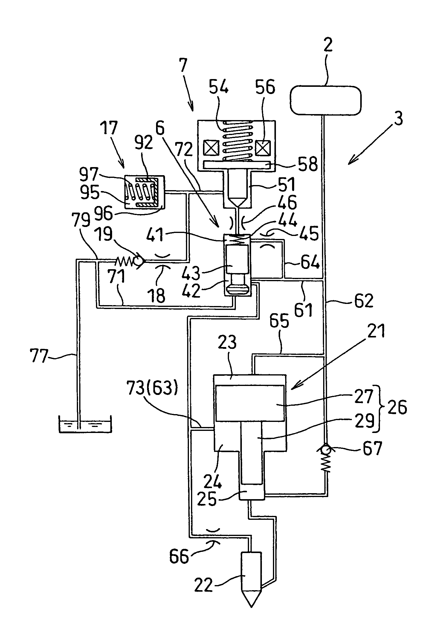
[0094]In the pressure intensifying piston type fuel injection apparatus of the present embodiment, the pressure fluctuation preventing unit 17 and the check valve 19 are arranged between the return pipe 77, which merges the flow of return fuel (including leak fuel) flowing out of the piston control chamber 24 of the pressure intensifier 21 of the injector 3 and the nozzle back pressure chamber 37 of the fuel injection nozzle 22 with the flow of fuel flowing out of the solenoid valve chamber 51 of the solenoid valve 7 and returns the flow of fuel collectively to the lower pressure side (fuel tank 9) of the fuel system, and the solenoid valve chamber 51 of the solenoid valve 7. With this construction, the pressure fluctuation of return fuel in the return pipe 77 does not propagate to the solenoid valve chamber 51 of the solenoid valve 7. Therefore, although the pressure intensifying piston type fuel injection apparatus of the present embodiment has an inex...

third embodiment

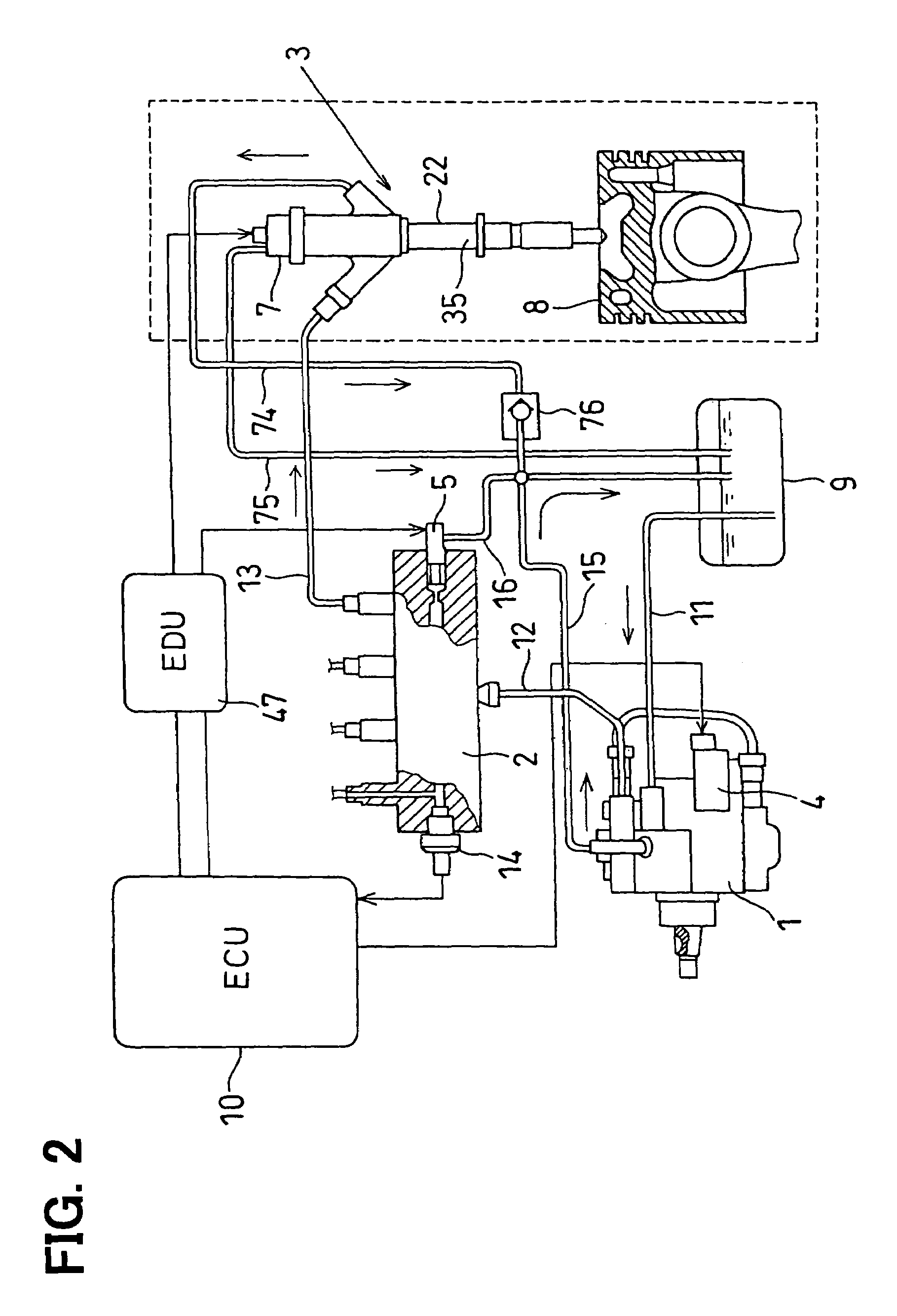
[0097]FIG. 7 and FIG. 8 shows third embodiment of the present invention. FIG. 7 is a configuration diagram showing the fuel piping system of a common rail type fuel injection system.

[0098]The injector 3 of the present embodiment has a first leak port open at the downstream end in the direction of flow of fuel of the first fuel discharge path 71 and the second leak port open at the downstream end in the direction of flow of fuel of the second fuel discharge path 72. A first return pipe 74 for returning surplus fuel flowing out of the respective injectors 3 (in particular, return fuel flowing out of the piston control chamber 24 of the pressure intensifier 21, and return fuel flowing out of the nozzle back pressure chamber 37 of the fuel injection nozzle 22) into the fuel tank 9 is connected between the first leak port of the injector 3 and the fuel tank 9. A check valve 76 for preventing the pressure fluctuation of return fuel in the first return pipe 74 is arranged in this first ret...


PUM


Abstract

A first fuel discharge path and a first return pipe that collectively discharge the amount of flow of fuel flowing out of the piston control chamber of a pressure intensifier built in an injector and the amount of flow of fuel flowing out of the nozzle back pressure chamber of a fuel injection nozzle (including the amount of flow of leak fuel) to a fuel tank and a second fuel discharge path and a second return pipe that discharge only the amount of flow of return fuel flowing out of the solenoid valve chamber of a solenoid valve are mounted separately from and independently of each other in terms of pipe line. With this measure, pressure in the solenoid valve chamber can be controlled to a value lower than the limit of resistance to pressure of an O-ring.

Description

CROSS-REFERENCE TO RELATED APPLICATION[0001]This application is based on Japanese Patent Application No. 2005-16547 filed on Jan. 25, 2005, the disclosure of which is incorporated herein by reference.FIELD OF THE INVENTION[0002]The present invention relates to a fuel injection apparatus for an internal combustion engine and, in particular, to a pressure intensifying piston type fuel injection apparatus provided with a pressure intensifier capable of intensifying the injection pressure of fuel injected from a fuel injection nozzle to a value more than the discharge pressure of fuel fed from a fuel supply pump.BACKGROUND OF THE INVENTION[0003]In recent years, for example, regulations on the cleaning of exhaust gas of a diesel engine have become severer and the combustion phenomenon of a diesel engine has been made clearer. With this, to reduce diesel particulates typified by black smoke for the purpose of cleaning exhaust gas exhausted from an engine, it is important to transform fuel...

Claims


Application Information

Patent Timeline
Patent Type & Authority Patents(United States)
IPC IPC(8): F02M57/00F02M57/02
CPCF02M47/027F02M57/025F02M63/0225F02M2200/315
Inventor SHIBATA, AKIRA
Owner DENSO CORP
Why Eureka
Try Eureka