Underwater vehicle deceleration and positive buoyancy assembly

a technology for underwater vehicles and positive buoyancy, which is applied in the direction of special-purpose vessels, tropedoes, transportation and packaging, etc., can solve the problems of reducing the possibility of having an affordable recovery system, excessive disassembly of the vehicle, and high cost of materials, so as to reduce the cost of flotation bags and less hydrodynamic loads

Inactive Publication Date: 2007-07-31
UNITED STATES OF AMERICA
View PDF5 Cites 16 Cited by
  • Summary
  • Abstract
  • Description
  • Claims
  • Application Information

AI Technical Summary

Benefits of technology

[0018]The method of inflating the flotation bags is by compressed gas. As depth increases, ambient pressure increases linearly. As pressure increases, the resulting volume of the inflated flotation bag decreases linearly, thus more gas is required at deeper depths to achieve the same volume. In many cases, the additional gas may not be available due to space limitations, thus rendering the recovery assembly useless at these deeper depths. Therefore, the hydrodynamic braking action of the doors reduces the time required to reach terminal velocity, thus reducing the depth the vehicle (or torpedo) sinks, thus enabling recovery with less gas required.
[0020]The releasing action of the latches allows the doors to open to the preset initial angle. Almost instantaneously, the packed pressure of the flotation bags acts against breakaway webs to assist the latches in setting the initial angle. The doors are further opened by ensuing hydrodynamic forces of the movement of the vehicle.
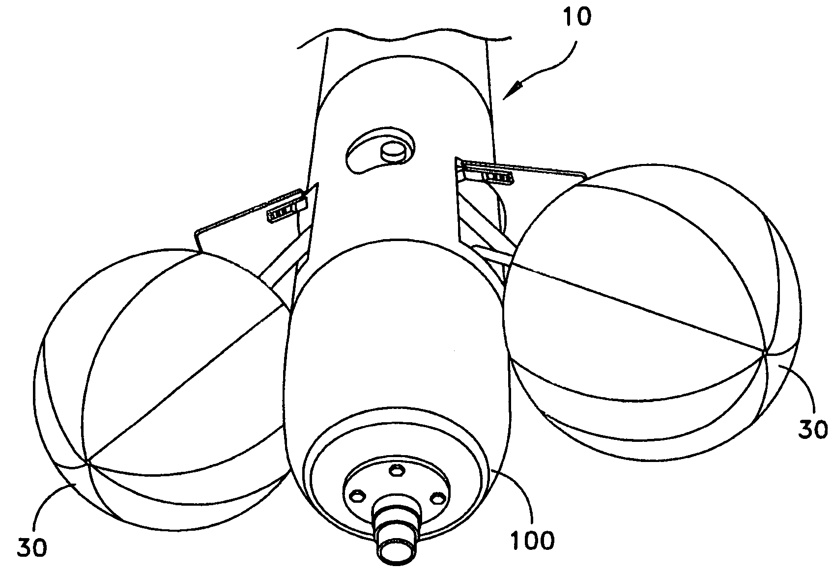
[0023]When the flotation bags are fully inflated, gas flow is allowed to pass through two high flow relief valves, limiting the pressure of each of the flotation bags thus preventing over-inflation of the flotation bags as the assembly rises to the ocean surface for recovery.
[0026]The doors can be deployed at high vehicle speeds, allowing for rapid deployment of the flotation bags at low vehicle velocities. The low vehicle velocities translate into lesser hydrodynamic loads on the flotation bags than other systems thereby greatly decreasing the cost of the flotation bags.

Problems solved by technology

The principle of buoyant bag recovery is straightforward, although complications arise for vehicles operating at speeds greater than 5 knots.
Under these circumstances, the forces are sufficient to damage the recovery bags, thus necessitating the use of exotic materials of construction for the bag.
The materials are typically expensive, all but negating the possibility of having an affordable recovery system.
Furthermore, in order to retrieve the undersea vehicle after recovery from the surface water and subsequently prepare the vehicle for another operation, the entire recovery assembly must be replaced from within the vehicle, requiring excessive disassembly of the vehicle, another undesirable cost driver.
At least one limitation on device of the Driggs reference is that the doors may further decelerate the torpedo but as a result of an initial deceleration.

Method used


Image

  • Underwater vehicle deceleration and positive buoyancy assembly
  • Underwater vehicle deceleration and positive buoyancy assembly
  • Underwater vehicle deceleration and positive buoyancy assembly

Examples


Embodiment Construction

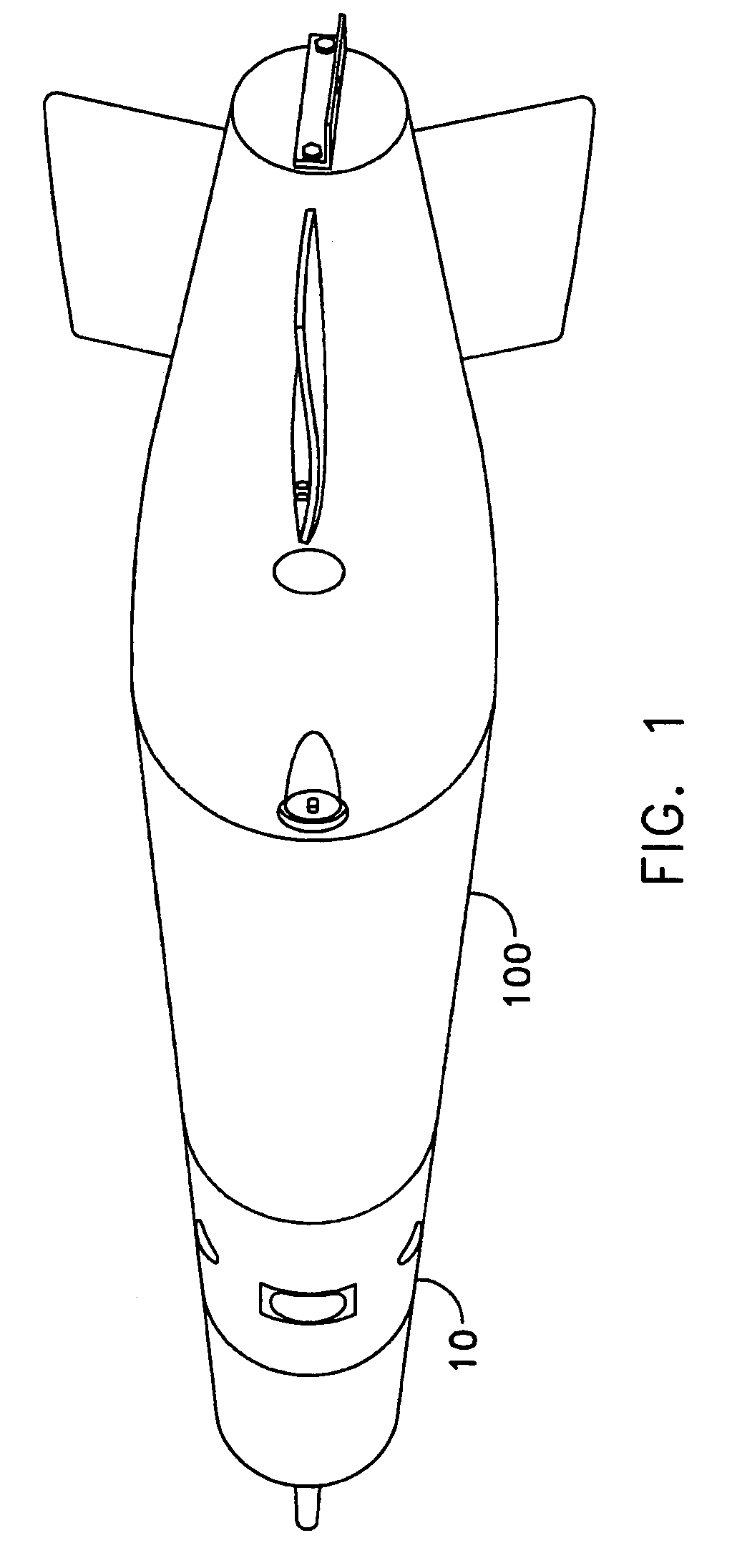
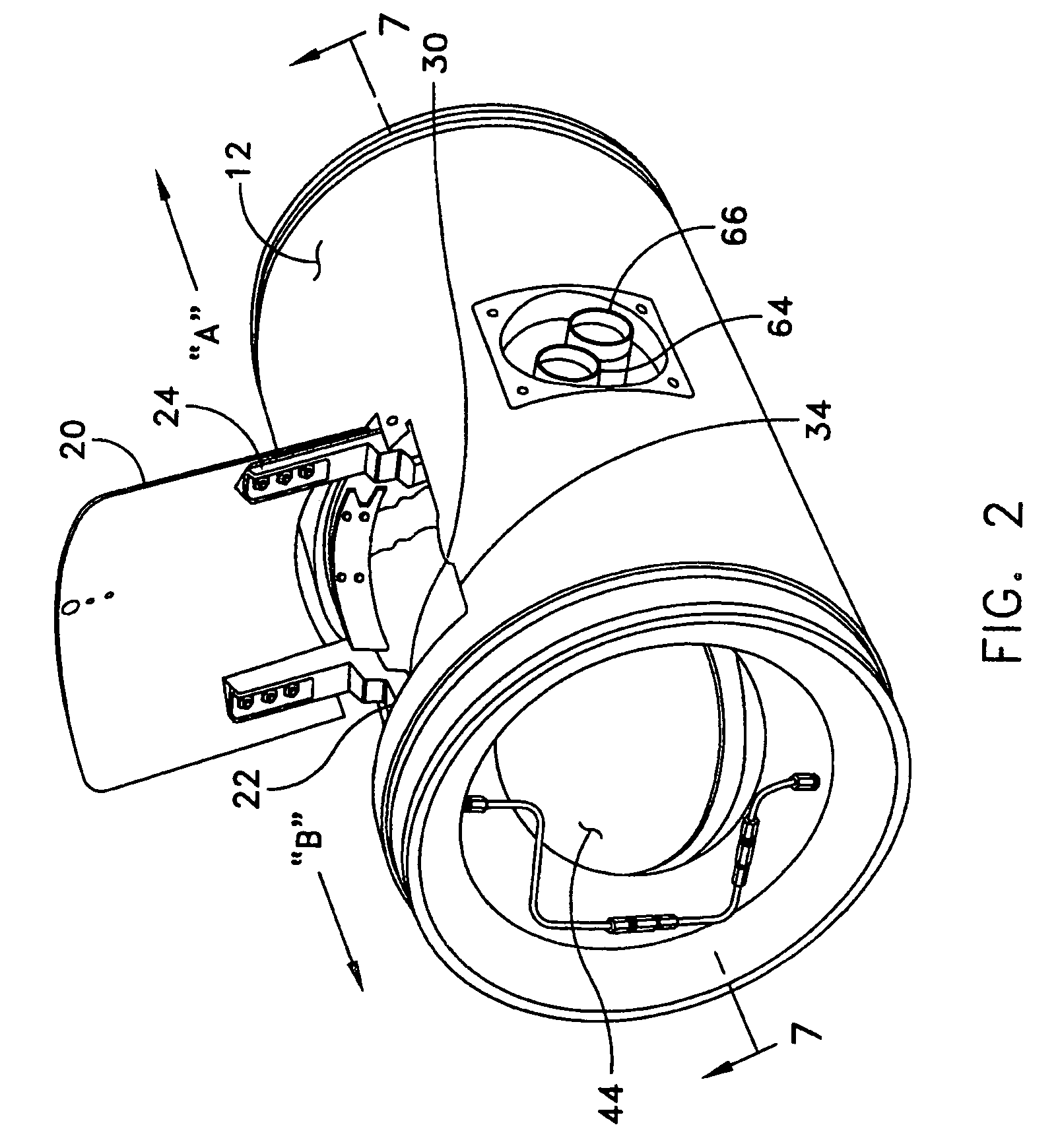
[0046]The vehicle deceleration and positive buoyancy assembly 10 of the present invention, hereinafter referred to the “assembly” is depicted in FIG. 1 as attached to a torpedo 100. The assembly 10 may be positioned on alternate undersea vehicles by modifying the assembly with methods that would be known to those skilled in the art. The assembly 10, shown in FIG. 2, prior to attachment to the torpedo 100, generally comprises a pair of doors 20 acting as pneumatically dampened hydrodynamic drag brakes with accompanying flotation bags 30 used for buoyant recovery of the torpedo. See FIG. 3 for the flotation bag 30 interior to the assembly 10 and secured by a break-away web 32; FIG. 4 for the flotation bag exterior to the assembly; and FIG. 5 for the flotation bags inflated and exterior to the assembly.

[0047]When recessed to a surface 12, the doors 20 act as concealing sleeves of the recovery flotation bags 30 and a storage cavity 34. The doors 20 (or systematically named hydrodynamic ...


PUM


Abstract

An assembly for vehicle deceleration and buoyancy comprises a pair of doors enclosing flotation bags inflatable for buoyant recovery of the torpedo. In operation, the doors are controllably forced open to an initial angle off a longitudinal axis of the assembly to a fully-deployed position by hydrodynamic forces of the movement of the vehicle. From the doors blocking the hydrodynamic forces, the vehicle decelerates. The hydrodynamic braking action of the doors reduces the time required to reach terminal velocity, thus reducing the depth the vehicle sinks and enabling recovery with less gas required for inflation.

Description

STATEMENT OF GOVERNMENT INTEREST[0001]The invention described herein may be manufactured and used by or for the Government of the United States of America for governmental purposes without the payment of any royalties thereon or therefor.BACKGROUND OF THE INVENTION[0002](1) Field of the Invention[0003]The present invention relates to describe a vehicle recovery assembly for underwater vehicles which operate under negatively buoyant conditions.[0004](2) Description of the Prior Art[0005]A variety of recovery systems for underwater vehicles have been in operation since submersibles were first conceived and operated. More recently, the Navy has operated vehicles employing recovery systems designed to bring negatively ballasted vehicles to the surface upon conclusion of vehicle operations.[0006]As indicated by the references that follow, present recovery systems rely on inflating bags (attached to the vehicle) with lower density gas or liquid, relative to seawater. The inflated bags pro...

Claims


Application Information

Patent Timeline
Patent Type & Authority Patents(United States)
IPC IPC(8): F42B19/00
CPCF42B10/50F42B19/44
Inventor DOW, ERIC G.HRUBES, JAMES D.
Owner UNITED STATES OF AMERICA
Why Eureka
Try Eureka