Cable clamp member for cable protective guide device

a technology of protective guide device and clamp member, which is applied in the direction of cable termination, insulated conductor, cable, etc., can solve the problems of slippage in motion between the stored cables, and achieve the effect of reducing manufacturing costs, reducing customer supply costs, and eliminating waste of parts

Active Publication Date: 2007-07-31
TSUBAKIMOTO CHAIN CO
View PDF7 Cites 4 Cited by
  • Summary
  • Abstract
  • Description
  • Claims
  • Application Information

AI Technical Summary

Benefits of technology

[0015]The present invention of the structure of the cable clamp member comprises the comb-tooth unit installation receiving member provided at the fixed end and at the moving end and including a plurality of engaged parts capable of changing the installation position of the clamp comb-tooth unit member in the width direction, and the clamp comb-tooth unit member to be detachably engaged with and installed to any one of the plurality of engaged parts to clamp a cable mounted in the installed state to the device.
[0016]According to the structure, preparation of a plurality of complicated dies can be dispensed with to reduce the manufacturing cost, since the clamp comb-tooth unit member and the comb-tooth unit installation receiving member can be separately constituted. Further, by separately constituting them, only a necessary number of comb-tooth unit members can be prepared according to the number of stored cables, and the waste of parts can be eliminated to reduce the providing cost to customers.
[0017]The present invention of the cable clamp member can have the following effect, since the plurality of engaged parts are provided on the comb-tooth unit installation receiving member at narrow intervals for minutely adjusting the installation pitch of the clamp comb-tooth unit member in addition to the structure of the first embodiment.
[0018]Namely, the clamp comb-tooth unit member can be installed to an optional engaged part according to the layout of stored cables since the installation pitch of the engaged parts for installing the comb-tooth unit installation receiving member is fine. Therefore, the stored cables can be surely clamped to the device flexibly in conformation to the layout of the stored cables, and the application of unreasonable force to the cables during movement of the device can be avoided to prevent the damage of the cables.
[0019]The present invention of the cable clamp member can have the following effect, since the respective engaged parts have the same fitting width, and the clamp comb-tooth unit member is prepared according to a plurality of sizes by providing an engagement part having a common width according to the fitting width and a cable mounting part having a size width according to different diameters of cables
[0020]Namely, a clamp comb-tooth unit member of different size can be optionally installed to any engaged part, since the width of the engagement part to be fitted to the engaged part of the comb-tooth unit installation receiving member is set to a common width usable in common to all the engaged parts, while a plurality of sizes are prepared for the width of the cable mounting part for mounting the cable of the clamp comb-tooth unit member according to the size of cable diameters. Therefore, the stored cables can be surely clamped to the device end part flexibly in conformation to the size or layout of cables to be stored, and the slippage in motion between the stored cables and the device during movement of the device can be suppressed to prevent the damage of the stored cables.

Problems solved by technology

In general, if a cable is protectively guided by this kind of cable protective guide device without clamping both ends of the stored cable to the cable protective guide device, respectively, slippage in motion is caused between the stored cable and the device, for example, when the device is moved in accordance with a moving part of an industrial machine, and the stored cable may be rubbed with the cable protective guide device or with another stored cable within a cable storage space and damaged by sliding wear or the like.

Method used


Image

  • Cable clamp member for cable protective guide device
  • Cable clamp member for cable protective guide device
  • Cable clamp member for cable protective guide device

Examples


example 1

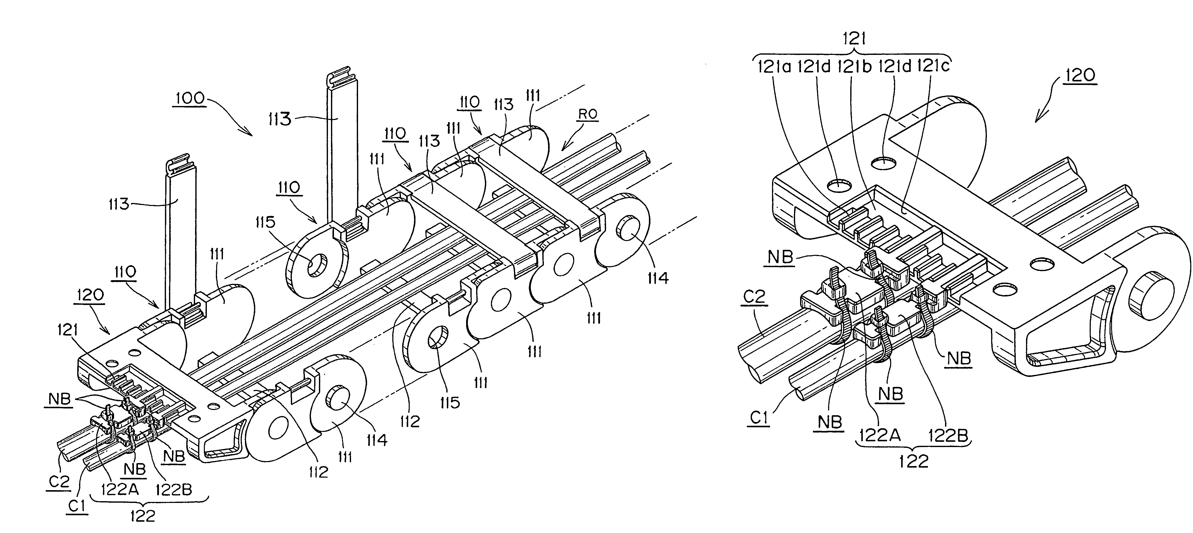
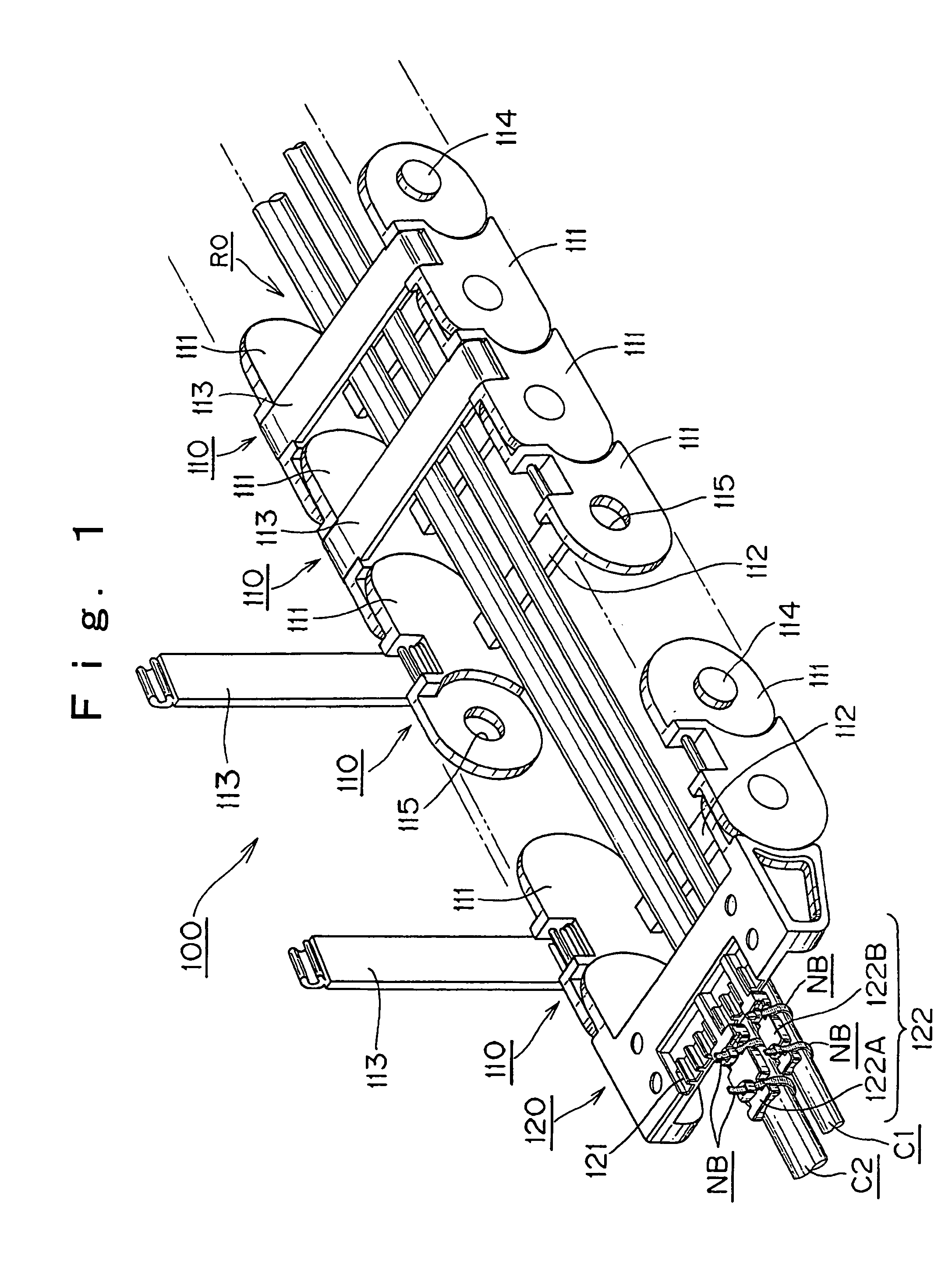
[0034]Example 1 of the cable clamp member of the present invention will be described with reference to FIGS. 1 to 3. FIG. 1 is a perspective view of a cable protective guide device 100 to which the cable clamp member of the present invention is applied. As shown in FIG. 1, the cable protective guide device 100 according to the present invention is used to protectively guide cables C (C1, C2) such as cables or hoses for supplying energy such as electric power or compressed air, for example, from a stationary part of an industrial machine (e.g., a semiconductor chip mounter, a machine tool, etc.) to a moving part of the machine, and formed by mutually connecting, for example, a number of rectangular link frame bodies 110 long, so that it can present a linear state or a bent state according the moving behavior between the moving part and the stationary part of the industrial machine not shown, and protectively guide the cables C (C1, C2) in a cable storage space RO continuously formed ...

example 2

[0051]Example 2 of the cable clamp member according to the present invention will be described with reference to FIGS. 4 to 6. Example 2 is characterized by a moving end of shelf receiving form (referred also to as a bracket) 220 and a fixed end not shown of the same structure as this moving end. Since the other main body part (the part where a plurality of link frame bodies are connected) has the same structure as Example 1 described above, the detailed description thereof is omitted while changing only the reference numbers thereof to 200s.

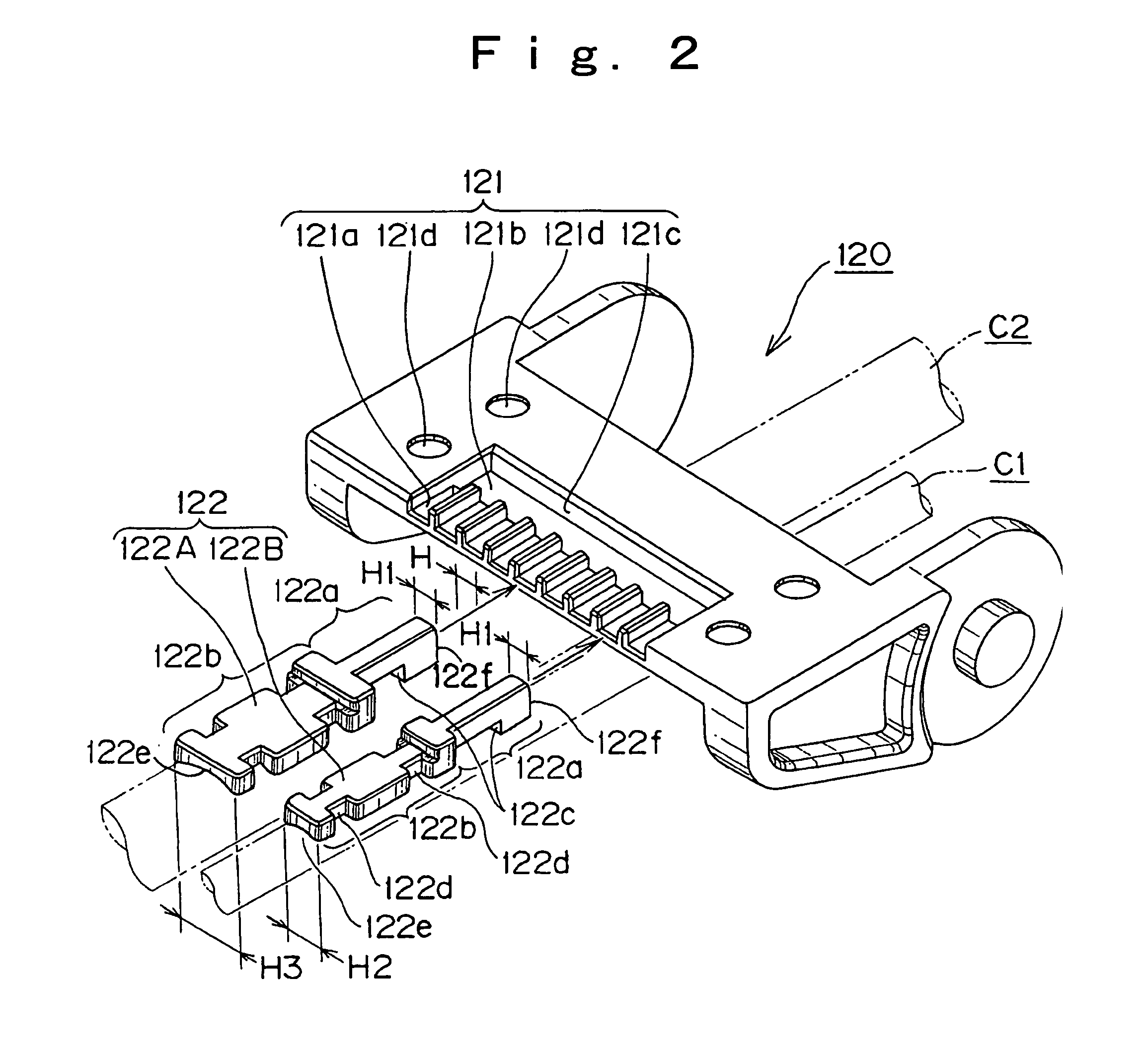
[0052]Namely, while the cable clamp member of Example 1 is adapted to engagingly install the comb-tooth 122 to the recessed-shaped engaged part 121a formed in the receiving member 121 of the moving end 120, the cable clamp member of Example 2 comprises a receiving member 221 having columnar projection-shaped engaged parts 221a instead of the recessed-shaped engaged parts 121 of Example 1, and a substantially bar-like comb-tooth 222 having a fitt...

example 3

[0066]Example 3 of the cable clamp member according to the present invention will be described with reference to FIG. 7. Example 3 shows a rectangular moving end 320 of clamp member two-stage structure, which comprises receiving members 321 (321A and 321B) of the same structure as the receiving member 121 shown in Example 1 described above, which are vertically provided in two stages of the bending outer circumferential side and the bending inner circumferential side of the cable protective guide device, and comb-tooth unit members 322 (322A and 322B, 322C and 322D) of the same structure as the comb-tooth 122 shown in Example 1 to be engagingly installed to the two-tiered receiving members 321 (321A and 321B), respectively. Since the other structure is the same as in Example 1, the detailed description thereof is omitted.


PUM


Abstract

The present invention provides a cable clamp member capable of reducing the providing cost or manufacturing cost of a device and surely clamping stored cables to a moving end or a fixed end flexibly in conformation to the size or layout of stored cables. The cable clamp member comprises a comb-tooth unit installation receiving member 121 provided on an end part 120 at a fixed end or a moving end and having a plurality of engaged parts 121a provided in a width direction so that a comb-tooth installation position is changeable, and a clamp comb-tooth unit member 122 to be detachably engaged with and installed to any one of the plurality of engaged parts to clamp a cable mounted in the installed state to the device. The plurality of engaged parts 121a are provided on the comb-tooth unit installation receiving member 121 at narrow intervals so as to minutely adjust the installation pitch of the clamp comb-tooth unit member 122.

Description

[0001]This patent application claims priority to Japanese Patent Application 2005-098742 filed Mar. 30, 2005.TECHNICAL FIELD[0002]The present invention relates to a cable protective guide device suitable for safely and surely protecting and guiding cables such as electric cables for transmitting electric signal or supplying electric power or hoses for supplying oil pressure or air pressure, which connect a moving part to a stationary part, for example, in an industrial machine, a semiconductor chip mounter, a vehicle or the like even during movement of the moving part, as well as storing the cables and, more specifically, relates to a cable clamp member used to clamp (fix) cables at a moving end or fixed end of the cable protective guide device.BACKGROUND ART[0003]Conventionally, as this kind of cable clamp member for cable protective guide device, a mounting unit provided on a chain member such as a moving end or fixed end located at an end part of the cable protective guide device...

Claims


Application Information

Patent Timeline
Patent Type & Authority Patents(United States)
IPC IPC(8): H02G15/02
CPCF16G13/16H01J37/32651H01J37/3411H01J2237/026
Inventor KOMIYA, SHOICHIRO
Owner TSUBAKIMOTO CHAIN CO
Why Eureka
Try Eureka