System for clock and data recovery

a clock and data recovery technology, applied in the field of data receivers, can solve the problem that the clock recovery occurs without prior knowledge of the expected data rate, and achieve the effect of high accuracy and no errors

Active Publication Date: 2007-07-31
CIENA
View PDF2 Cites 9 Cited by
  • Summary
  • Abstract
  • Description
  • Claims
  • Application Information

AI Technical Summary

Benefits of technology

[0008]The present invention includes a clock and data recovery (CDR) system that generates one or more clock signals from a received data stream and determines an optimal clock signal to associate with the incoming data stream. For example, in a receiver system, an incoming data stream may be provided without a corresponding clock signal so that only one signal is received. One or more embodiments included in the present invention operate to generate the optimal clock for the data stream and lock the generated clock to the data so that downstream processing systems are able to process the received data with high accuracy and without errors.

Problems solved by technology

Furthermore, the clock recovery occurs with no prior knowledge of the expected data rate.

Method used


Image

  • System for clock and data recovery
  • System for clock and data recovery
  • System for clock and data recovery

Examples


Embodiment Construction

[0019]The present invention includes a system for determining an optimal clock to associate with a received data stream. For example, in a system where the received data stream is not accompanied by synchronizing clock signal, the system operates to process the received data stream to generate candidate clock signals and select the optimal candidate clock to use to further process the incoming data stream. Thus, various embodiments of the system included in the present invention are discussed in detail in the following text.

EXEMPLARY EMBODIMENT

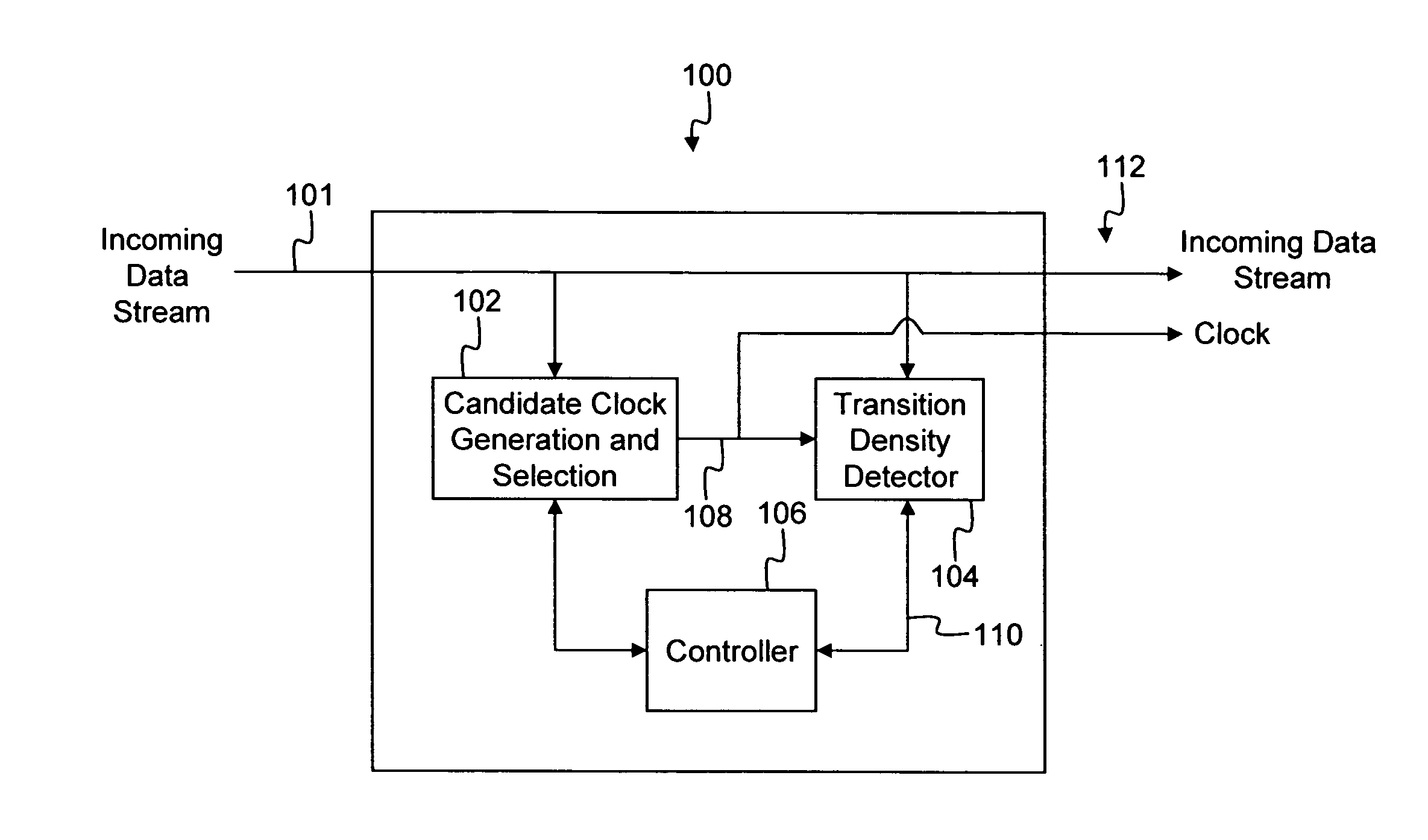
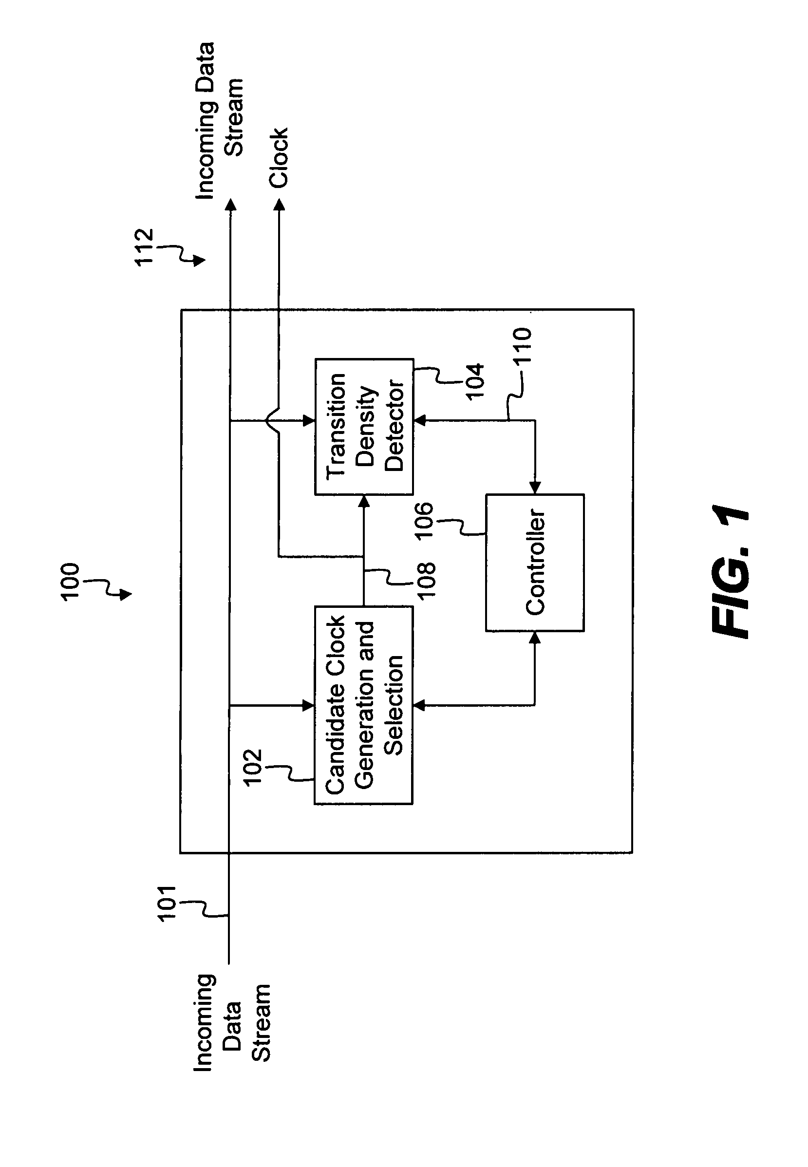
[0020]FIG. 1 shows an overview of a system 100 for clock recovery constructed in accordance with the present invention. The system 100 receives as input a data stream 101 that does not have a corresponding clock signal. For example, the input data stream may be encoded in an NRZ format so that only a signal data stream is received.

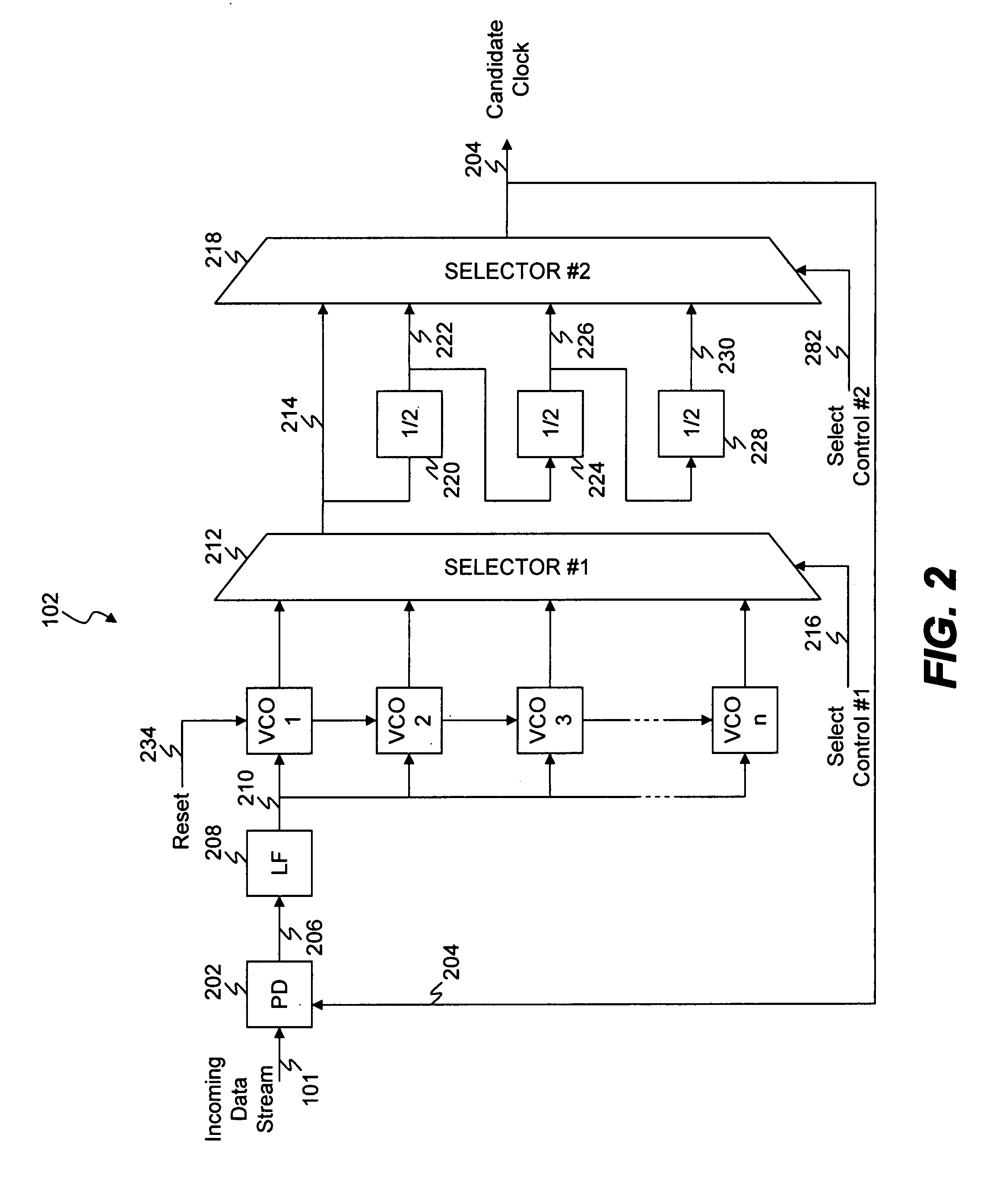
[0021]The system 100 includes candidate clock generation and selection logic 102, transition detector logic 104 an...


PUM


Abstract

A clock and data recovery (CDR) system that generates one or more clock signals from a received data stream and determines an optimal clock signal to associate with the incoming data stream. The system includes a candidate clock generation circuit that operates to receive the incoming data stream and generate candidate clock signals. A transition density detector circuit determines a transition density parameter associated with each of the candidate clock signals. A controller operates to determine the optimal clock signal based on the transition density parameters.

Description

FIELD OF THE INVENTION[0001]The present invention relates generally to data receivers, and more particularly, to a system for use in a data receiver to recover a clock signal from a received data stream.BACKGROUND OF THE INVENTION[0002]Optical networks are becoming widely used for distributing both high and low speed data over varying distances. Typically, an optical network is comprised of a number of network elements (NE) that are connected to each other in a variety of configurations so as to form a unified communication network. The communication network may extend over a small area, such as a company wide network, or may cover large distances, such as in regional or nationwide networks. Typically, the NE's allow network clients to input data for transmission over the network and to receive data transmitted over the network from other locations. Thus, data may be added or dropped from the network at NE locations as the data flows from point to point throughout the network.[0003]...

Claims


Application Information

Patent Timeline
Patent Type & Authority Patents(United States)
IPC IPC(8): H03D3/18H03D3/24H03L7/099H04L7/033H04L25/02
CPCH03L7/099H04L7/033H04L25/0262H04L7/0332
Inventor KENNEDY, CHRISHENRIQUEZ, CARLOSHESTER, KEVIN
Owner CIENA
Why Eureka
Try Eureka