Eureka AIR delivers breakthrough ideas for toughest innovation challenges, trusted by R&D personnel around the world.

Optical isolator with tilted optical isolator element

a technology of optical isolators and optical isolators, which is applied in the field of optical isolators, can solve the problems of reverse propagation loss, wavelength deviation, fluctuation in output power, etc., and achieve the effect of low insertion loss

Inactive Publication Date: 2007-07-31
KYOCERA CORP
View PDF12 Cites 4 Cited by
  • Summary
  • Abstract
  • Description
  • Claims
  • Application Information

AI Technical Summary

Benefits of technology

[0013]An object of the present invention is to provide an optical isolator that is capable of correcting the shifting of light beam due to the optical isolator element and can be easily assembled and adjusted.
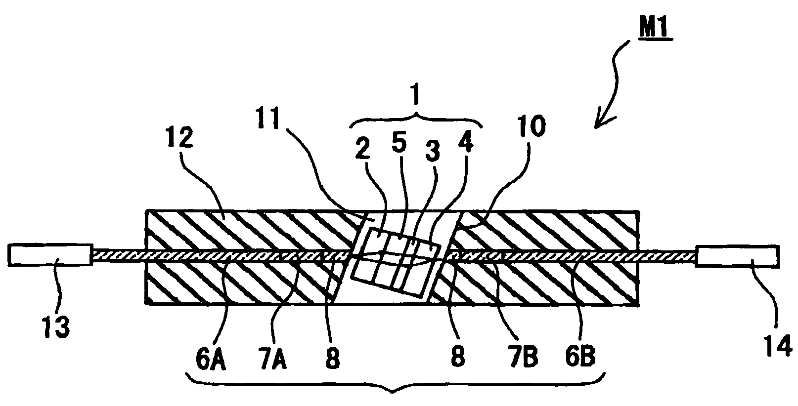
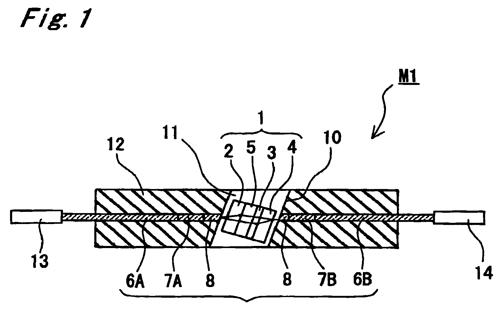
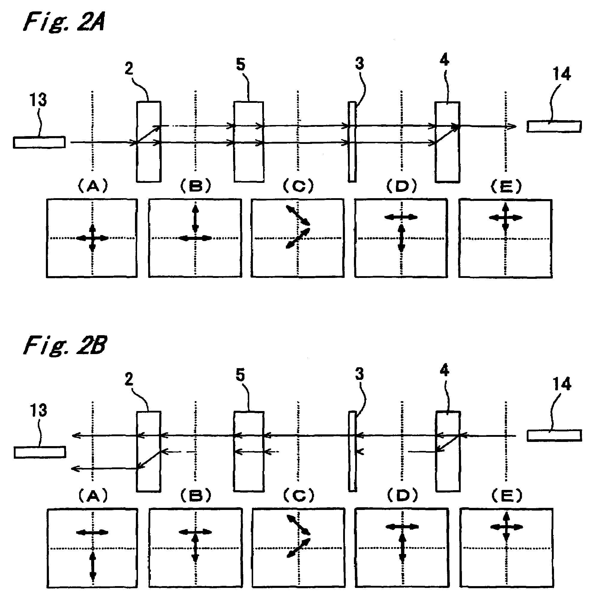
[0019]According to the present invention, beam shift within the optical isolator element can be effectively corrected by tilting the optical isolator element with respect to the optical axis, so as to achieve optical coupling with both the end face of the first graded index fiber on the coreless fiber side and the end face of the second graded index fiber on the coreless fiber side. The present invention also provides the optical isolator that is small in size and is easy to assemble, without causing misalignment between the optical fibers on the input and output sides.
[0021]The groove may be inclined, by the same angle as the optical isolator element is tilted, with respect to the optical axis of the optical fiber assembly. This makes it easier to adjust the tilting angle of the optical isolator element when assembling the optical isolator.
[0022]It is preferable to fill the groove with a light transmitting filler. It is particularly preferable that the refractive index of the light transmitting filler is from 0.94 to 1.06 times as large as the refractive index of the coreless fiber. With this configuration, since there is almost no difference in the refractive index between the coreless fiber and the light transmitting filler at the interface thereof, sufficient level of reflection attenuation can be ensured regardless of the tilting angle of the end face of the coreless fiber (that is, even when the end face is not tilted). Also because the light ray hardly refracts even when the end face of the coreless fiber is tilted, there is less effect of the variation in the tilting angle of the end face of the coreless fiber on the insertion loss, and allowance margin for adjusting the tilting angle of the optical isolator element increases. As a result, an optical isolator having smaller insertion loss can be easily manufactured.
[0024]This enables it to provide the optical isolator having low insertion loss.

Problems solved by technology

A laser diode (hereinafter abbreviated as LD) used in optical communications or optical measurements, when reflected light returning from the outside enters an active layer of the LD, experiences the collapse of internal interference leading to such troubles as wavelength deviation and fluctuation in the output power.
As a consequence, there is generated a deviation in position from the input optical fiber 13, thus resulting in a reverse propagation loss.

Method used


Image

  • Optical isolator with tilted optical isolator element
  • Optical isolator with tilted optical isolator element
  • Optical isolator with tilted optical isolator element

Examples


example 1

[0052]An example of the present invention will now be described with reference to FIG. 1.

[0053]The optical fiber assembly 9 was made by fusing and connecting the quartz-based single mode fiber 6A having mode field diameter of 10 μm, 0.8 mm of the graded index fiber 7A having core diameter of 105 μm and difference in the refractive index of 0.55%, 2 mm of the coreless fiber 8 made of pure quartz, 0.8 mm of the graded index fiber 7B having similar parameters as those of the graded index fiber 7A and the single mode fiber 6B successively in this order.

[0054]Then with a through hole formed in the support body 14 made of zirconia in advance, the optical fiber assembly 9 was inserted into the through hole and secured therein with an epoxy-based thermosetting adhesive 11.

[0055]The entire support body 12 together with the coreless fiber 8 portion of the optical assembly 9 was then cut off by dicing, thereby to form the groove 10 at an angle of 1 degree from the optical axis.

[0056]The first ...


PUM


Abstract

An optical isolator including: (a) a support body; (b) an optical fiber assembly disposed in the support body including a first single mode fiber, a first graded index fiber, a coreless fiber, a second graded index fiber, and a second single mode fiber; and (c) an optical isolator element disposed in a groove formed in the support body so as to separate the coreless fiber. The optical isolator element is tilted with respect to the optical axis of the optical fiber assembly, thereby to achieve optical coupling with both the end face of the first graded index fiber on the coreless fiber side and the end face of said the graded index fiber on the coreless fiber side.

Description

BACKGROUND OF THE INVENTION[0001]1. Field of the Invention[0002]The present invention relates to an optical isolator that utilizes nonreciprocity and, more particularly, to a polarization independent optical isolator particularly suitable for optical communications.[0003]2. Description of the Related Art[0004]An optical isolator has directivity in its function so as to allow forward propagation of light but blocks backward propagation of light. A laser diode (hereinafter abbreviated as LD) used in optical communications or optical measurements, when reflected light returning from the outside enters an active layer of the LD, experiences the collapse of internal interference leading to such troubles as wavelength deviation and fluctuation in the output power. In order to prevent the reflected light from returning so that the LD maintains stable oscillation, an optical isolator that prevents light from propagating backward is used. The optical isolator is indispensable in such applica...

Claims


Application Information

Patent Timeline
Patent Type & Authority Patents(United States)
IPC IPC(8): G02B6/26
CPCG02B6/2746
Inventor SATO, YASUSHI
Owner KYOCERA CORP
Why Eureka
Eureka Blog
Learn More