Method for generating a network map

a network map and network technology, applied in the field of network map generation, can solve the problems of poor turnaround time, noisy measurement to the endpoint, and potentially stale mapping on successive requests, and achieve the effect of reducing the size of the network map

Inactive Publication Date: 2007-07-31
AKAMAI TECH INC
View PDF26 Cites 82 Cited by
  • Summary
  • Abstract
  • Description
  • Claims
  • Application Information

AI Technical Summary

Benefits of technology

[0010]In a preferred embodiment, the method relies on a network map that is generated continuously for the user-base of the entire Internet. The problems inherent in the prior art are overcome by vastly reducing the dimensionality of the problem of estimating the relative connectivity to a set of mirrored data centers. A “data center” is typically located at a telecommunications facility that leases space and sells connectivity to the Internet. Multiple content providers may host their web sites at a given data center. Instead of probing each local name server (or other host) that is connectable to the mirrored data centers, the network map identifies connectivity with respect to a much smaller set of proxy points, called “core” (or “common”) points. A core point then becomes representative of a set of local name servers (or other hosts) that, from a data center's perspective, share the point. Each set of mirrored data centers has an associated map that identifies a set of core points.
[0013]A full network map is created by generalizing a core point / data center data set to an IP block / data center data set. This “unification” fills in and reduces the size of the network map and enables traffic redirection to be carried out for new local name servers.
[0014]The generated network map is then used to effect traffic redirection and load balancing. In particular, when a user's local name server makes a request for the content provider's web site (located within a set of mirrored data centers), the method preferably uses the network map to return to the local name server a list of web server IP addresses at the optimal data center. If ping data is not available for the user's local name server (of it the IP block has not been extended through unification), BGP or geo-routing can be used to make a default routing decision. Content provider-specified load balancing preferences may also be readily enforced across the data centers and / or within a particular data center.

Problems solved by technology

This technique can lead to poor turnaround time during an initial “hit” and potentially stale mappings on successive requests.
In addition, the quality of the measurement to the endpoint tends to be noisy.
Because of the deficiencies of these mapping techniques, the resulting load balancing is less than effective.
Current load balancing devices are typically incapable of computing an optimal map for an entire computer network such as the entire Internet.
Estimating the connectivity time of the entire Internet to a set of mirrored data centers, such as by evaluating the network path between a server and each and every host or router, would be incredibly time-consuming and would consume far too much bandwidth.
Such techniques, of course, are impractical when real-time routing decisions are required.
Further, such measurements tend to be noisy and inaccurate, and they can annoy system administrators whose firewalls are contacted.
Local name servers behind firewalls would not be reached and slow connectivity over the “last mile” (e.g., due to dial-up connections and the like) tend to confuse the connectivity picture.
Consequently, there remains no efficient technique in the prior art for generating an optimal network connectivity map that can be used for providing intelligent traffic redirection in conjunction with load balancing across mirrored data centers located around the globe.

Method used


Image

  • Method for generating a network map
  • Method for generating a network map
  • Method for generating a network map

Examples


Embodiment Construction

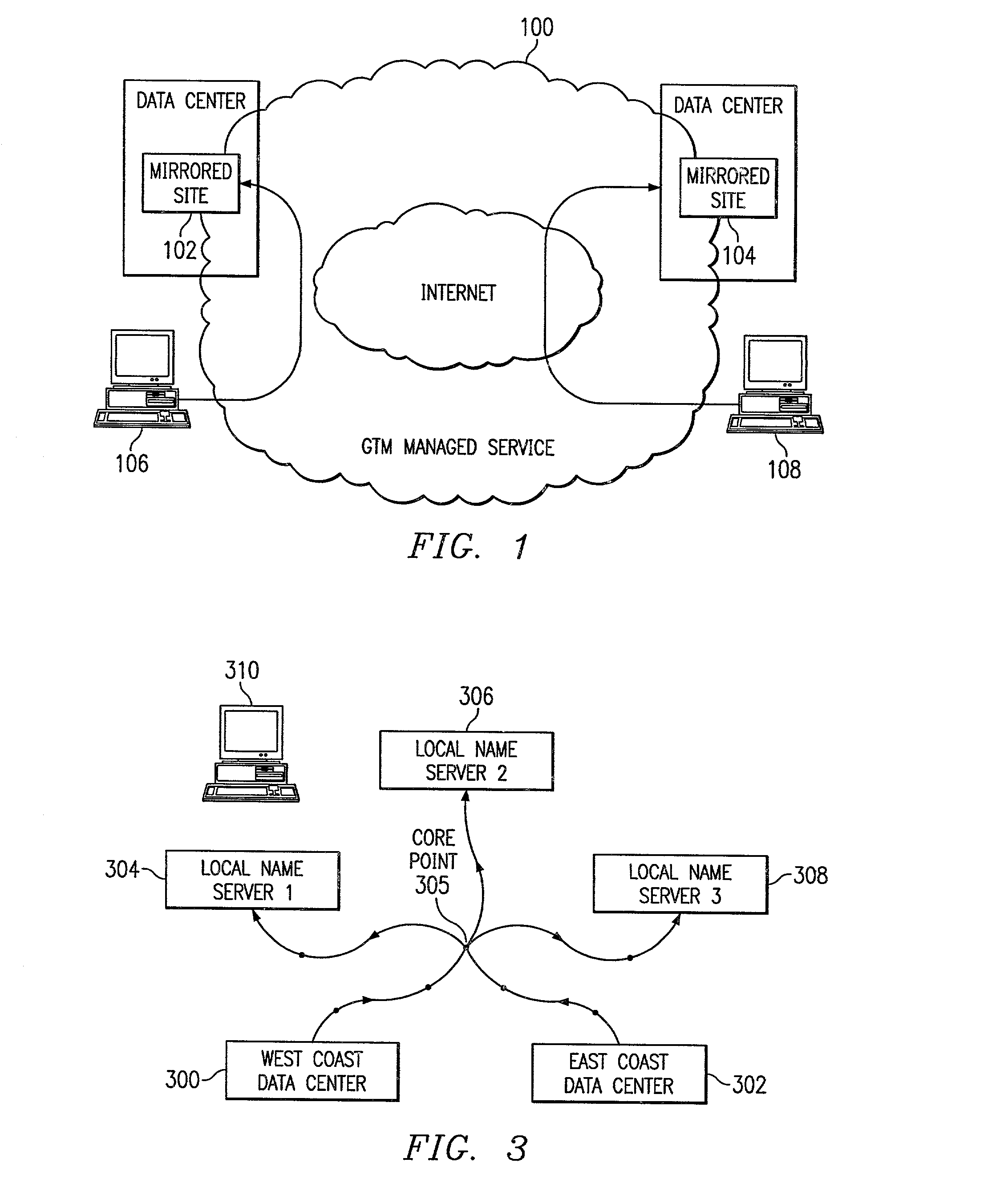
[0025]By way of brief background, it is known in the art for a Web content provider to distribute or “mirror” its Web site to ensure that the site is always available and providing acceptable performance for a global customer base. Once a Web site is distributed, global traffic management (GTM) solutions typically are used to direct users to the various mirror sites. GTM solutions use a variety of methods to determine which is the “best” mirrored site in which to direct a user. Because Internet conditions are constantly changing, however, the “best” site for a particular user also varies with these conditions. The present invention is a GTM solution that maximizes availability and performance of a mirrored delivery site.

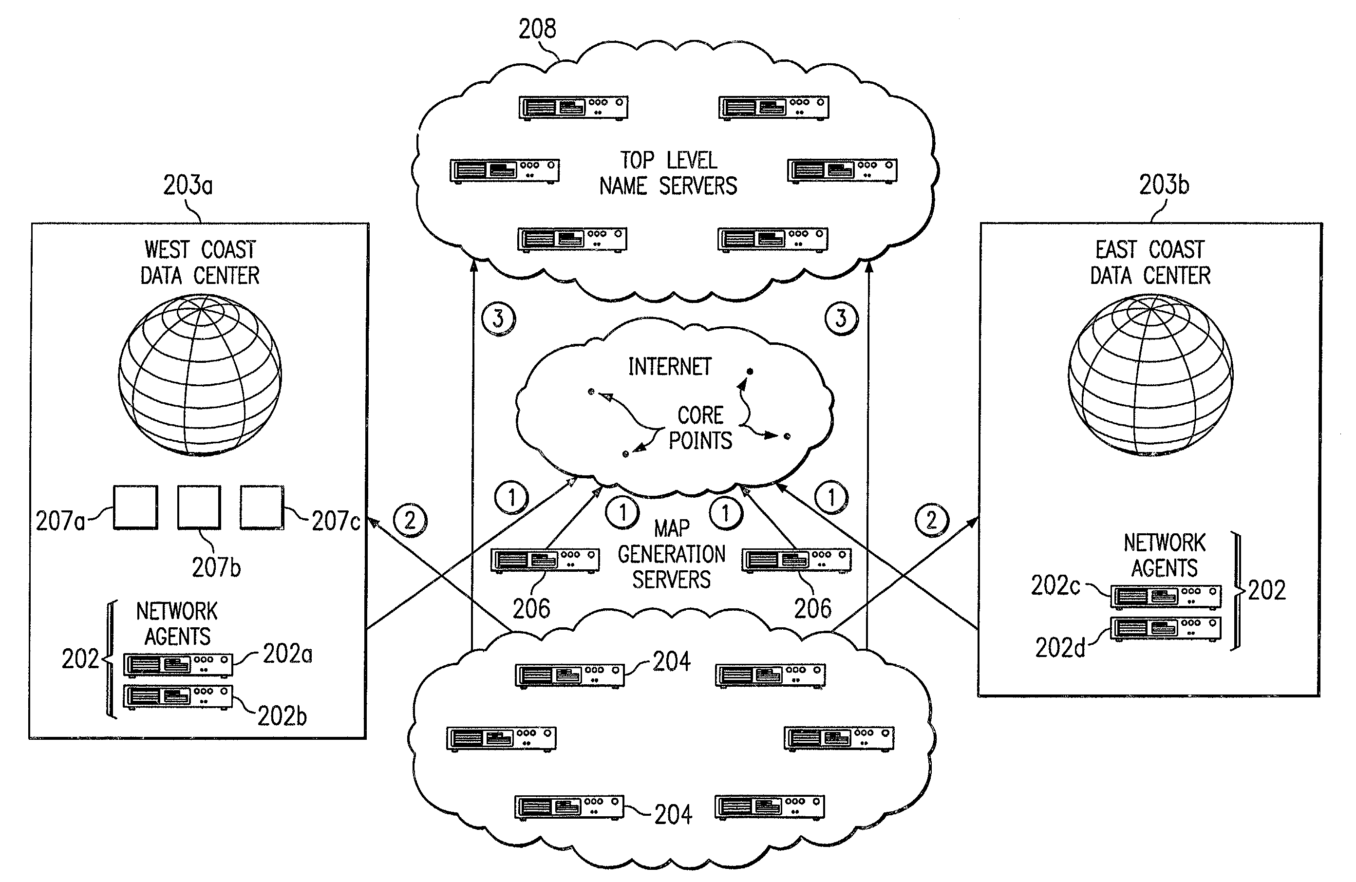
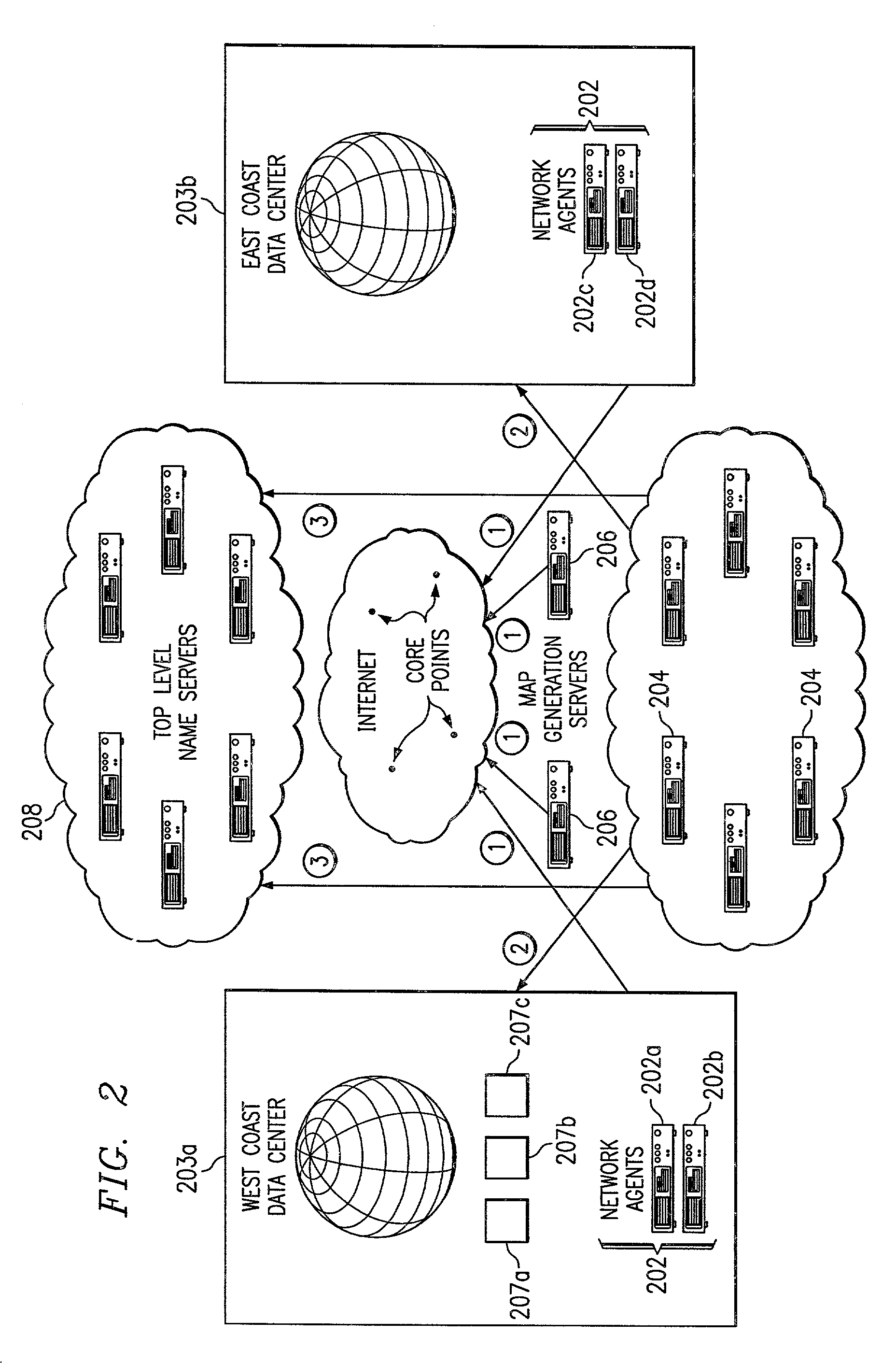
[0026]In a preferred embodiment now described, the global traffic management solution is a managed service provided by a service provider, such as a content delivery network (CDN) service provider (CDNSP). As is well-known, a CDN is a network of geographically distri...


PUM


Abstract

An intelligent traffic redirection system performs global load balancing for Web sites located at mirrored data centers. The system relies on a network map that is generated continuously, preferably for the user-base of the entire Internet. Instead of probing each local name server (or other host) that is connectable to the mirrored data centers, the network map identifies connectivity with respect to a much smaller set of proxy points, called “core” (or “common”) points. A core point is representative of a set of local name servers (or other hosts) that, from a data center's perspective, share the point. To discover a core point, an incremental trace route is executed from each of the set of mirrored data centers to a local name server that may be used by client to resolve a request for a replica stored at the data centers. An intersection of the trace routes at a common routing point is then identified. Thus, for example, the common routing point may be the first common point for the trace routes when viewed from the perspective of the data centers (or the last common point for the trace routes when viewed from the perspective of the local name server). The common routing point is then identified as the core point for the local name server.

Description

[0001]This application is based on and claims priority from Provisional Application Ser. No. 60 / 208,014, filed May 26, 2000.RELATED APPLICATIONS[0002]This application is related to the following commonly-owned applications: “Global Load Balancing Across Mirrored Data Centers,” Ser. No. 09 / 866,897, filed May 29, 2001; “Method For Predicting File Download Time From Mirrored Data Centers In A Global Computer Network,” Ser. No. 09 / 867,141, filed May 30, 2001; and “Method For Extending A Network Map,” Ser. No. 09 / 866,896, filed May 29, 2001.BACKGROUND OF THE INVENTION[0003]1. Technical Field[0004]The present invention relates generally to high-performance, fault-tolerant content delivery and, in particular, to systems and methods for balancing loads from mirrored data centers within a global computer network.[0005]2. Description of the Related Art[0006]It is known to store Web-based content in mirrored data centers and to load-balance such content requests to data centers based on networ...

Claims


Application Information

Patent Timeline
Patent Type & Authority Patents(United States)
IPC IPC(8): G06F15/173H04L12/26H04L12/56H04L29/06H04L29/08H04L29/12
CPCH04L12/2697H04L29/12066H04L43/50H04L61/1511H04L67/1008H04L67/101H04L67/1002H04L69/329H04L67/2814H04L61/4511H04L67/1001H04L67/563
Inventor LEIGHTON, F. THOMSONSUNDARAM, RAVILEVINE, MATTHEWSOVIANI, ADRIAN
Owner AKAMAI TECH INC
Why Eureka
Try Eureka