Method and apparatus for defining leading edge taper of a write pole tip

a technology of write pole tip and taper, which is applied in the field of magnetic storage system, can solve the problems of poor reliability attributes, high power consumption, and relative slow response of any mechanical system, and achieve the effects of minimizing ati, reducing power consumption, and increasing the effective write field

Inactive Publication Date: 2007-08-07
HITACHI GLOBAL STORAGE TECH NETHERLANDS BV
View PDF16 Cites 45 Cited by
  • Summary
  • Abstract
  • Description
  • Claims
  • Application Information

AI Technical Summary

Benefits of technology

[0019]The present invention solves the above-described problems by providing a fabrication process that uses reactive ion etching to fabricate LET with tight control of the placement of LET's edge and to achieve higher angle for providing a higher effective write field at the pole tip while minimizing ATI for high-density perpendicular recording. The placement of a resist's edge is used to define the LET's edge and a chemical mechanical polishing (CMP) process is used to provide a planar surface for the fabrication of the write pole.

Problems solved by technology

In order to obtain the relatively low cost of today's storage system compared to solid state memory, the customer must accept the less desirable features of this technology, which include a relatively slow response, high power consumption, noise, and the poorer reliability attributes associated with any mechanical system.
On the other hand, magnetic storage systems have always been nonvolatile; i.e., no power is required to preserve the data, an attribute which in semiconductor devices often requires compromises in processing complexity, power-supply requirements, writing data rate, or cost.
While nature allows us to scale down the size of each bit of information, it does not allow scaling to happen forever.
Today, as the magnetic particles that make up recorded data on a storage system become ever smaller, technical difficulties in writing and reading such small bits occur.
Today it is becoming more challenging to increase areal densities in longitudinal recording.
However, this has proven to be challenging because the ability to simultaneously control both flare point and track-width using ion milling approach is difficult due to the physical nature of this destructive method.
Equally challenging in “bringing” the flux guide layer closer to the ABS is ATI issues.
Controlled methods using ion mill approach to fabricate LET in the past have proven to be of great difficulty to simultaneously achieve both optimal LET angle, tight placement of the LET's edge and couple this process into P3 fabrication to define LET's width at the ABS to minimize ATI issues.

Method used


Image

  • Method and apparatus for defining leading edge taper of a write pole tip
  • Method and apparatus for defining leading edge taper of a write pole tip
  • Method and apparatus for defining leading edge taper of a write pole tip

Examples


Embodiment Construction

[0034]In the following description of the embodiments, reference is made to the accompanying drawings that form a part hereof, and in which is shown by way of illustration the specific embodiments in which the invention may be practiced. It is to be understood that other embodiments may be utilized because structural changes may be made without departing from the scope of the present invention.

[0035]The present invention provides a method and apparatus for defining leading edge taper of a write pole tip. The present invention provides a fabrication process that uses reactive ion etching to fabricate LET with tight control of the placement of LET's edge and to achieve higher angle for providing a higher effective write field at the pole tip for high density perpendicular recording.

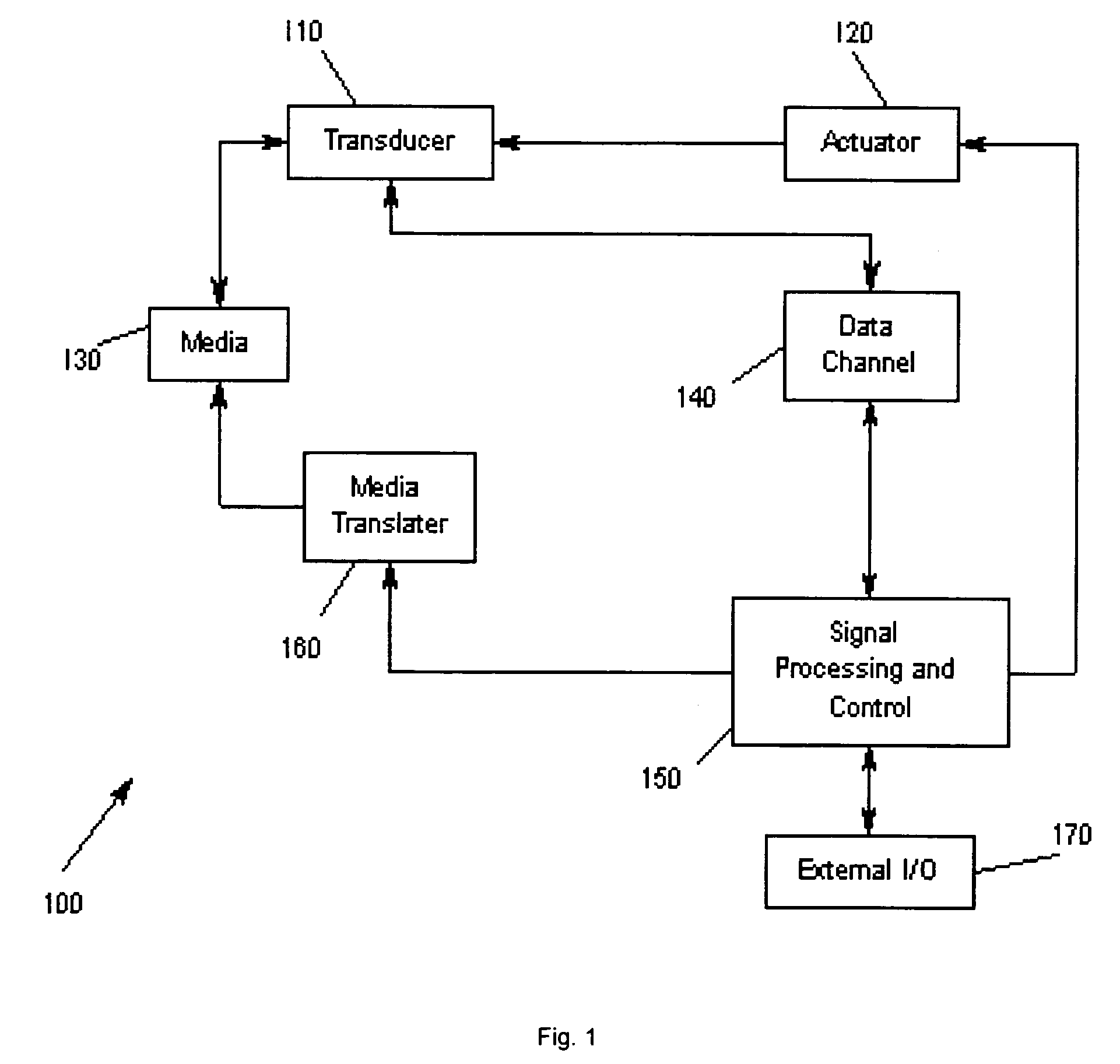
[0036]FIG. 1 illustrates an exemplary storage system 100 according to the present invention. A transducer 110 is under control of an actuator 120, whereby the actuator 120 controls the position of the trans...


PUM

PropertyMeasurementUnit
angleaaaaaaaaaa
tapering angleaaaaaaaaaa
angleaaaaaaaaaa

Abstract

A method and apparatus for defining leading edge taper of a write pole tip is disclosed. The fabrication process uses reactive ion etching to fabricate LET with tight control of the placement of LET's edge and to achieve higher angle for providing a higher effective write field at the pole tip while minimizing ATI for high-density perpendicular recording. The placement of a resist's edge is used to define the LET's edge and a CMP process is used to provide a planar surface for the fabrication of the write pole.

Description

BACKGROUND OF THE INVENTION[0001]1. Field of the Invention[0002]This disclosure relates in general to magnetic storage systems, and more particularly to a method and apparatus for defining leading edge taper of a write pole tip.[0003]2. Description of Related Art[0004]There has been huge progress in the field of magnetic storage system technology in almost 50 years. Moreover, the rate of this progress is increasing year after year. Such success has made storage systems an important component of modern computers.[0005]Some of the most important customer attributes of any storage system are the cost per megabyte, data rate, and access time. In order to obtain the relatively low cost of today's storage system compared to solid state memory, the customer must accept the less desirable features of this technology, which include a relatively slow response, high power consumption, noise, and the poorer reliability attributes associated with any mechanical system. On the other hand, magneti...

Claims


Application Information

Patent Timeline
Patent Type & Authority Patents(United States)
IPC IPC(8): G11B5/187B44C1/22
CPCG11B5/1278G11B5/3163Y10T29/49052Y10T29/49048Y10T29/49046Y10T29/49043Y10T29/49041
Inventor LE, QUANGLI, JUI-LUNGWINTON, YVETTE CHUNG NGAZHANG, SUE SIYANGZHENG, YI
Owner HITACHI GLOBAL STORAGE TECH NETHERLANDS BV
Why Eureka
Try Eureka