Lightweight building component

a building component and light weight technology, applied in the direction of building components, load-supporting elements, structural elements, etc., can solve the problems of prone structure to possible future corrosion of steel reinforcement contained in concrete slabs, difficult corrosion and costly repair, etc., to achieve low cost, low cost, and easy installation of structural members

Inactive Publication Date: 2007-08-07
RAY T FORMS
View PDF21 Cites 7 Cited by
  • Summary
  • Abstract
  • Description
  • Claims
  • Application Information

AI Technical Summary

Benefits of technology

[0029]Any of the three embodiments described above can be fabricated with the top horizontal wall being somewhat lower than the uppermost portion of the side walls, thus forming a small U-shaped recipient chamber to be filled later with a fluid mix that sets with a modulus of elasticity several times that of the PVC alloy of the element, cement mortar, for example. In such a case, the top wall may have extensions like fingers pointing upwards that, together with the ends of the side walls, will hold the layer of material poured on the top tied to the PVC alloy contact surface, to both perform in bending as one integral structural composite. To better accomplish this purpose, the side walls and those upward projections have dovetail-shaped ends. The projections from the top wall can be shorter than the side wall ends to perform as resting means for steel reinforcement that may be needed inside the poured top layer. That reinforcement may be the same common flat type wire reinforcement used between the courses of masonry walls. These modified top configurations easily and economically form what may be considered a general fourth embodiment having longitudinally over 2.5 times the bending stiffness and over 1.7 times the bending strength of the corresponding unmodified embodiment.
[0030]The present invention provides various features. For example, the invention provides lightweight, thermoplastic structural formwork members constructed and arranged to be interconnected in a series to serve as formwork for ribbed concrete slabs. Also, the invention provides inexpensive and easy to install structural members for use in constructing ribbed concrete slabs. Further, formwork for ribbed concrete slabs that forms a continuous impervious structure is provided, thus eliminating the needs for exterior waterproofing membranes when used in roof construction. Moreover, the invention provides formwork having a longitudinal and transverse flexural strength and stiffness sufficient to resist the weight of the wet concrete and the vertical and lateral construction loads, yet needing few transverse intermediate temporary supports while the concrete cures. The invention further provides a ribbed concrete formwork having a pleasant appearing exposed surface capable of being used as a finished ceiling with a smooth finish or with embossing that can be formed during the extrusion process at little or no extra cost. The invention also facilitates hung ceiling installation in commercial and institutional buildings where it is necessary to have a plenum for heating and air-conditioning pipes and duct work above the ceiling. The formwork provides outward indicia or other markings indicative of areas in which hanging measures for the ducts and pipes may be located with assurance of sufficient holding strength of easily penetrated material, for example, to screw in hangers for the hung ceiling, ducts, and pipes. The present invention also facilitates installation of thermal insulation for the ribbed slab and accurate and easy installation of steel reinforcing bars and / or splice bars in association with the formwork before pouring of the concrete. Also provided is the construction of ribbed reinforced concrete slabs using about one-half the normal weight and volume of concrete as compared to conventional construction and forming techniques.

Problems solved by technology

It, thus, avoids the leakage of concrete mortar through formwork joints during concrete pouring and cure time, which leakage can result in honeycomb void defects that cause the structure to be prone to possible future corrosion of steel reinforcement contained in the concrete slab.
Such corrosion is often difficult and costly to repair.

Method used


Image

  • Lightweight building component
  • Lightweight building component
  • Lightweight building component

Examples


first embodiment

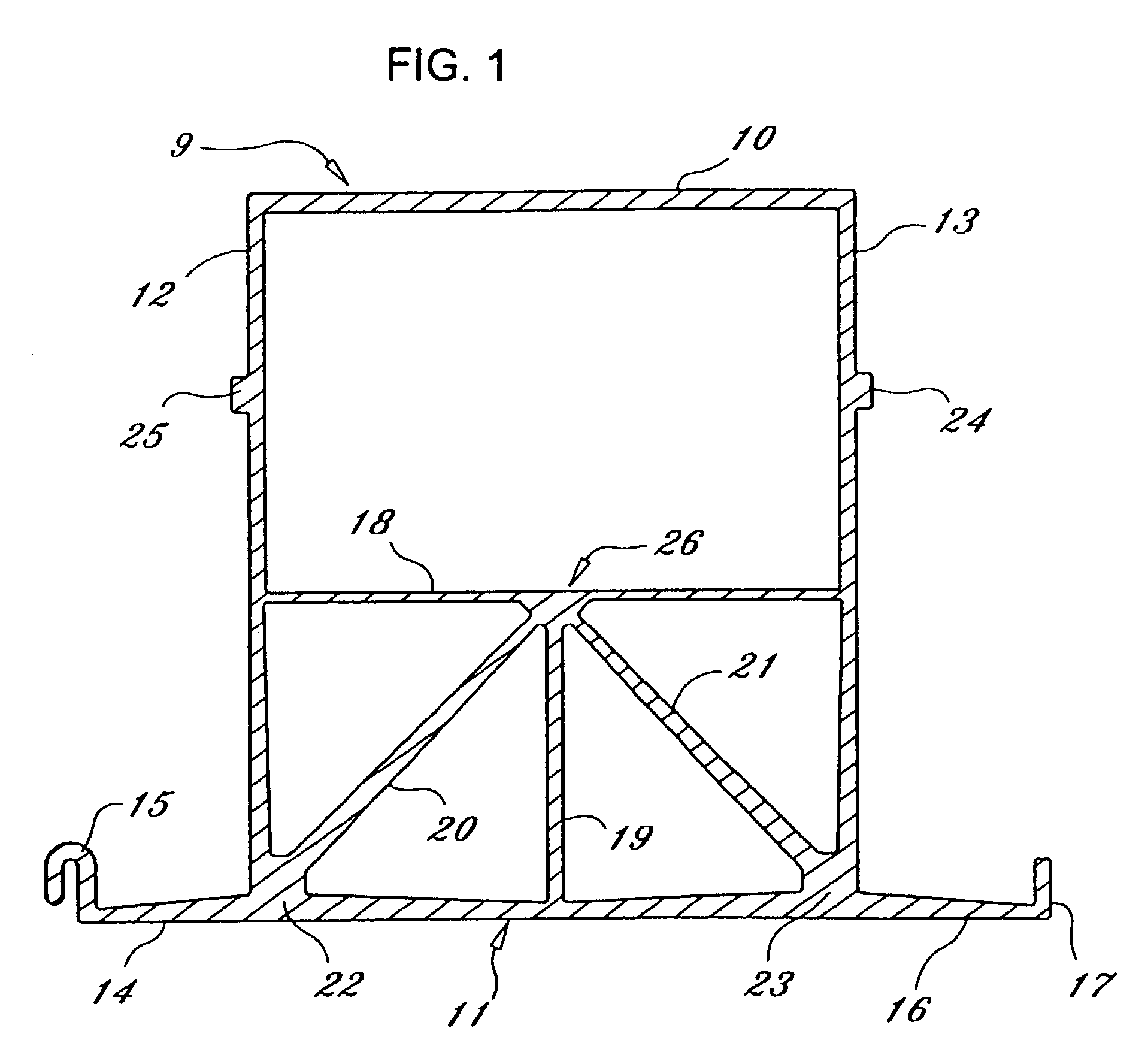
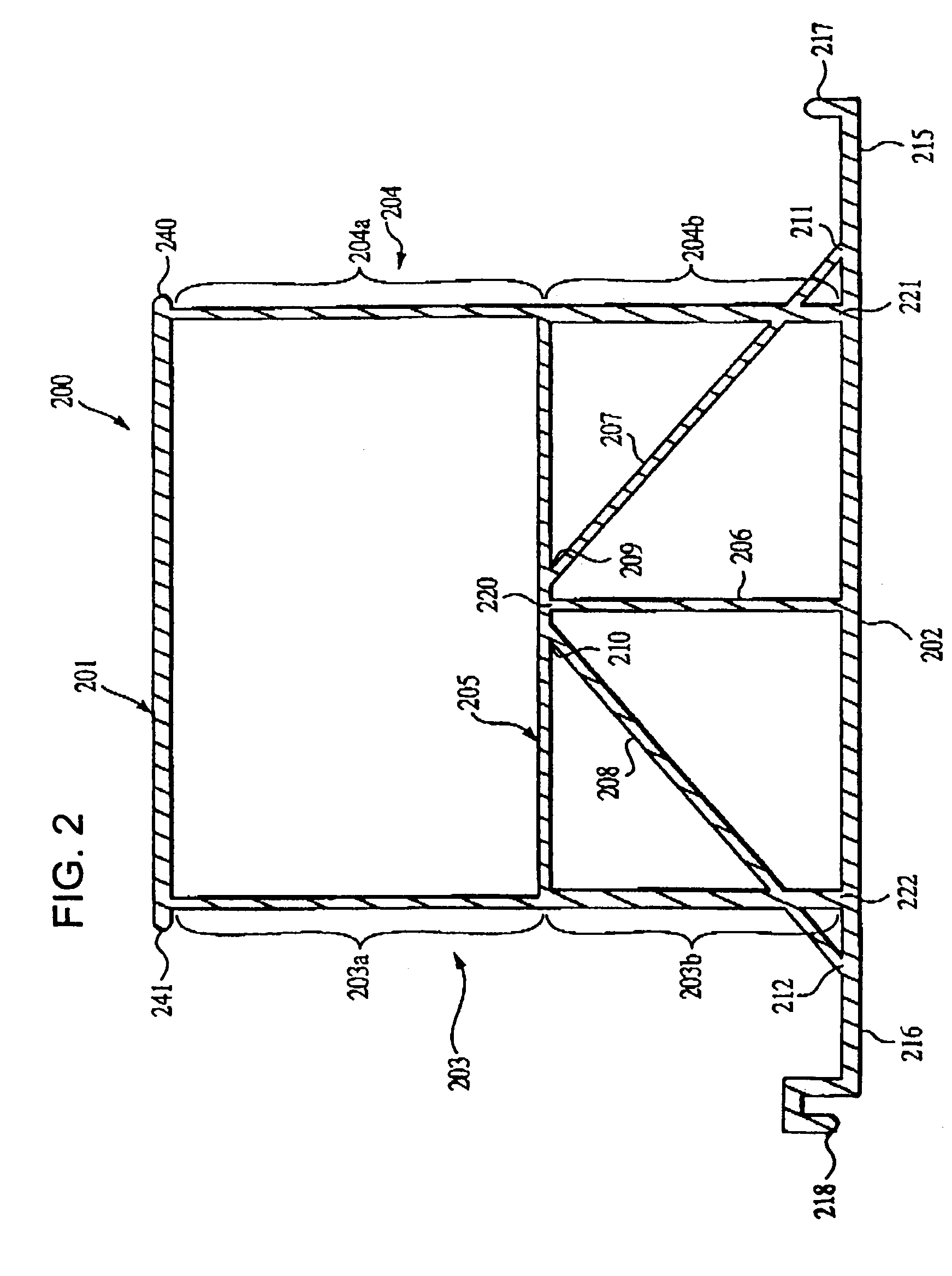
[0064]In the embodiment of FIG. 2, the tensors 207, 208 intersect the wings at points 211, 212, respectively, which should be proximate to the bottom left and right intersections 221, 222. The tensors cover a portion of the wings between the bottom left and right intersections 221, 222 and points 211, 212 and form a triangle that is void of concrete. The portions of the side walls (below the intersection of the tensors with the side walls) and the portion of the wings between 211, 212 and 221, 222 respectively, are kept small to make these portions very rigid. As a result, the points from which the wings cantilever is from points 211, 212 to the free ends of the wings. The result is that the bending moment at the attached end of the cantilever (points 211, 212) and the deflection at the tip of the free end of the wings is greatly reduced. Therefore, there is no need to taper any wall or wing as there is in FIG. 1.

[0065]To further increase rigidity of the section of the member below ...

third embodiment

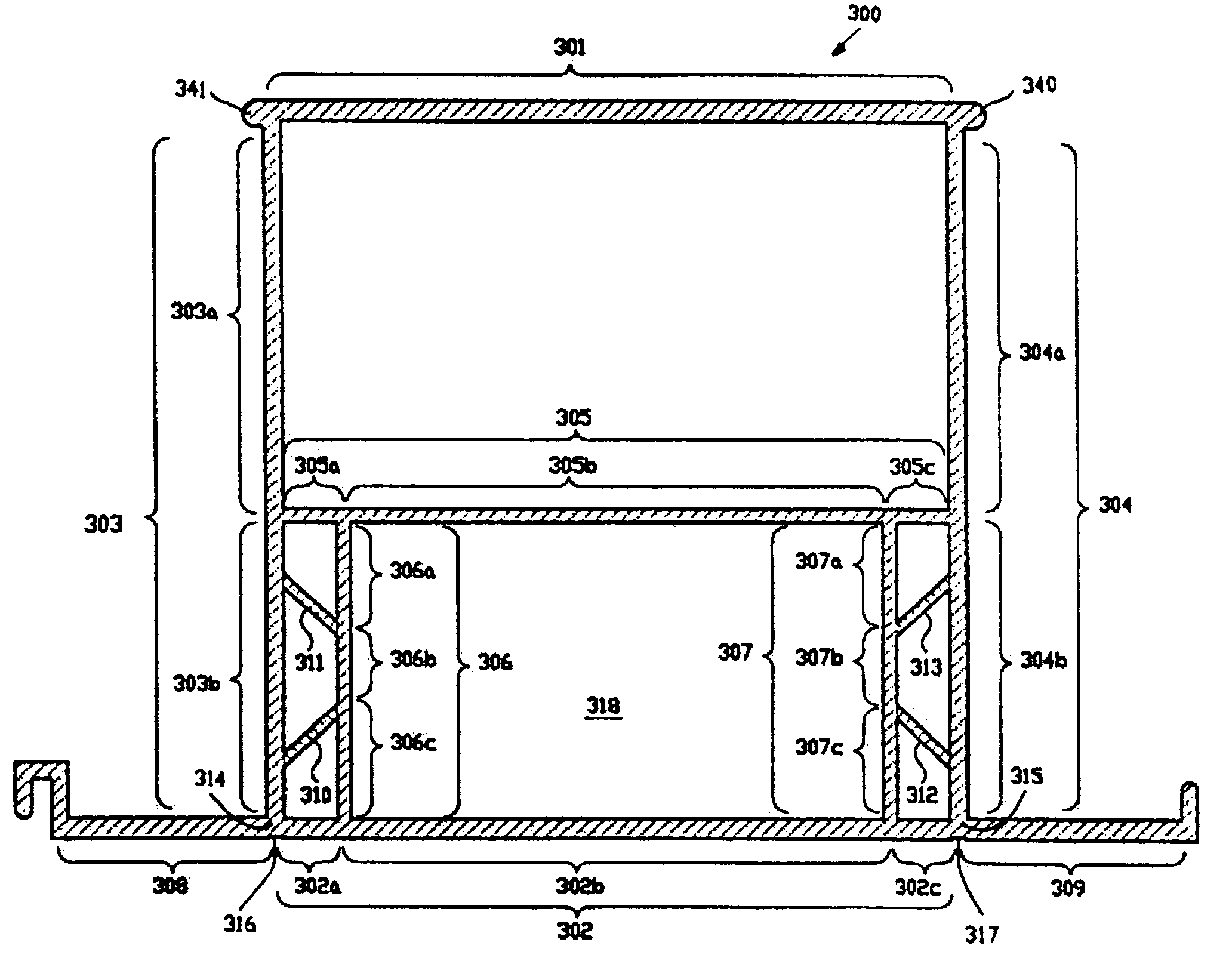
[0070]The embodiment of FIG. 3 has a top side or wall 301, a bottom wall 302, and opposed parallel side walls 303 and 304. There is a horizontal wall 305 centrally located on the member 300, parallel to the top wall 301 and to the bottom wall 302. There are two vertical walls 306, 307, interconnected between the bottom wall 302 and the horizontal wall 305, extending from the horizontal wall 305 at symmetrical points nearer to the opposing side walls 303, 304 than to a line defining the midpoint between the side walls 303, 304, each of the vertical walls 306, 307 extending from the horizontal wall 305 to the bottom wall 302. The total web of longitudinal internal walls is completed by four inclined walls 310, 311, 312, 313 each shorter than the span of one of the vertical walls 306, 307, each pair of the inclined walls 310, 311 and 312, 313 respectively extending from ends of a central segment 306b, 307b of each of the vertical walls 306, 307 to the nearby side wall 303, 304. The inc...

fourth embodiment

[0077]FIG. 6 illustrates a preferred fourth embodiment of a tubular structural member 600 according to the invention.

[0078]The design of this fourth embodiment is the same as the third embodiment of FIGS. 3 and 5 except that it has a different upper portion. Specifically, the top horizontal wall 601 is lower than the top end of the side walls 603, 604, thereby creating side wall fingers 613, 614 extending up from the top wall 601. Accordingly, a small U-shaped recipient chamber 602 is created that can be filled later with a fluid mix that sets. The addition of the setting fluid (i.e., cement mortar) to the member 600 increases the modulus of elasticity of the member 600 to several times that of the PVC alloy of the member 300. It is noted that the moment of inertia of the embodiment of FIG. 7 with the chamber 602 filled with material 702 and reinforcement 703, 704 is more than 2.5 times greater than the embodiment of FIG. 3.

[0079]FIG. 7 is a preferred configuration for the fourth em...


PUM


Abstract

A structural member includes side walls, a top wall connecting a top region of the side walls, a bottom wall connecting side wall bottoms and extending beyond the side walls to form wings each having one portion of a connector for connecting members to one another, a span connected to the side walls, and truss configurations each connected to the span and the bottom wall and respectively to one side wall. Side walls, top wall, and span define an upper interior chamber and span, truss configurations, and bottom wall define a lower interior chamber. Each truss configuration has a vertical wall and two intermediate walls. An assembly of members interlock with one another in series by connecting a first portion of the connector with a second portion of another member. These interlocked members form a structure for receiving concrete as a base for a ribbed concrete slab.

Description

CROSS-REFERENCE TO RELATED APPLICATION[0001]This application is a continuation-in-part of allowed application Ser. No. 10 / 075,187 filed on Feb. 14, 2002, now U.S. Pat. No. 6,668,512 which is a continuation-in-part of application Ser. No. 09 / 433,593 filed on Nov. 2, 1999 now abandoned.BACKGROUND OF THE INVENTION[0002]1. Field of the Invention[0003]This invention relates to a single very light tubular building element for the construction of reinforced concrete intermediate floors / ceilings and roofs. The single building element provides the formwork for the casting in place of the structural concrete and also provides for a high quality finished ceiling at the same time. It is intended for simple installation without heavy equipment into building parts. A series of members are often intended to form an exposed surface when used as a floor or ceiling.[0004]A series of members are constructed and often disposed to be the primary means of containing and supporting a panel or slab of conc...

Claims


Application Information

Patent Timeline
Patent Type & Authority Patents(United States)
IPC IPC(8): E04B2/08E04C3/00E04C5/10E04B5/19E04C3/02E04C3/28
CPCE04B5/19E04C3/02E04C3/28
Inventor RAY, MANUEL A.
Owner RAY T FORMS
Why Eureka
Try Eureka