
Image processing apparatus and method for efficiently compressing and encoding still images and motion pictures

Inactive Publication Date: 2007-08-07
CANON KK
View PDF3 Cites 3 Cited by
  • Summary
  • Abstract
  • Description
  • Claims
  • Application Information

AI Technical Summary

Benefits of technology

[0036]It is an object of the present invention to provide an image processing apparatus and method that can efficiently compress and encode both still images and motion pictures with a simple structure.

Problems solved by technology

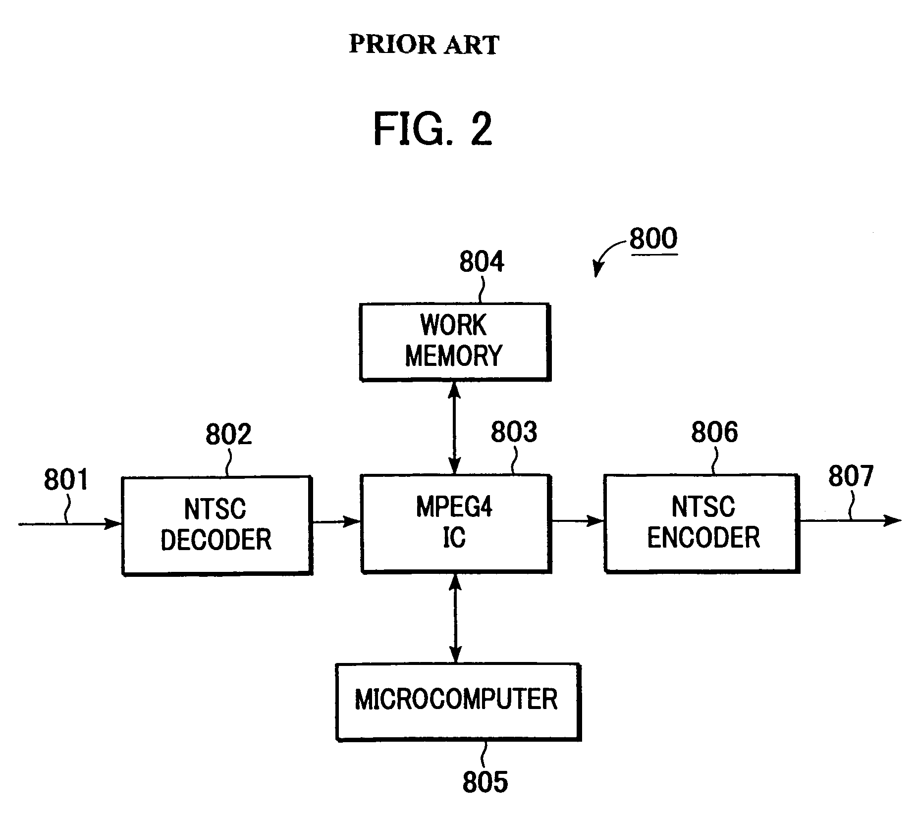
However, the capacity of the work memory 705 is limited.
Therefore, limited specifications, such as the size of the image data to be recorded being not larger than the video graphics array (VGA) size (640×480 pixels), the frame rate being not higher than 15 fps, and the continuous photographing period being limited 30 seconds, are provided.
Hence, the resolution and the frame rate of the motion pictures are restricted because of the limited capacity of a work area or a detachable storage medium, such as a compact flash (CF) card or a secure digital (SD) card, and thus motion pictures can be captured only for a short period.

Method used


Image

  • Image processing apparatus and method for efficiently compressing and encoding still images and motion pictures
  • Image processing apparatus and method for efficiently compressing and encoding still images and motion pictures
  • Image processing apparatus and method for efficiently compressing and encoding still images and motion pictures

Examples


first embodiment

[0050]A first embodiment of the present invention is an image processing apparatus 100 shown in FIG. 3.

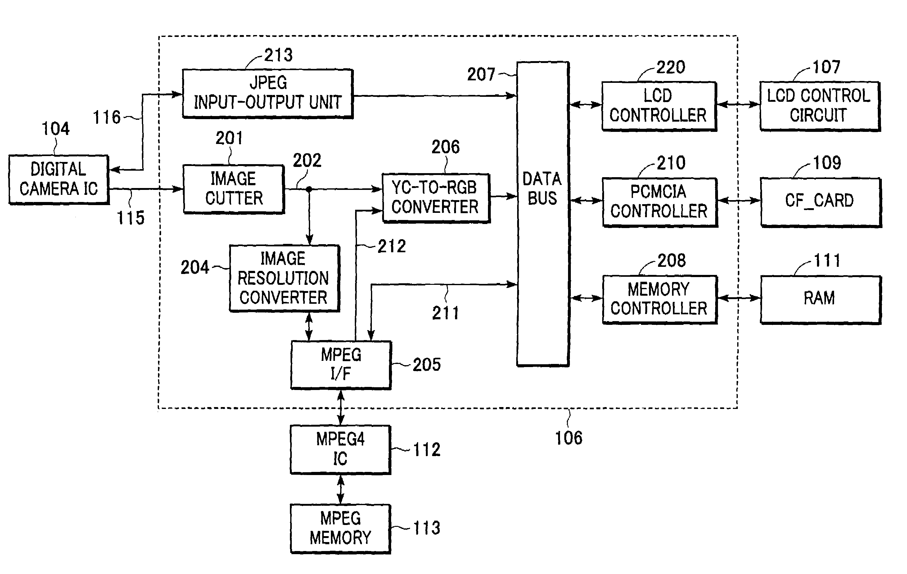
[0051]The image processing apparatus 100 of the first embodiment cuts out image data required for finder display from data that is supplied from a digital camera IC 104 and switches between conversion from the cut image data (effective image data) to a display data format and conversion from the cut image data to a data format that can be input to a compression IC at any size.

[0052]The structure and operation of the image processing apparatus 100 of the first embodiment will now be described.

Overall Structure of the Image Processing Apparatus 100

[0053]Referring to FIG. 3, the image processing apparatus 100 includes a lens unit 101, a CCD 102, a CCD control unit 103, the digital camera IC 104, a camera memory 105, a central processing unit (CPU) 106, a liquid crystal display (LCD) control circuit 107, a thin film transistor (TFT) liquid crystal display 108, a CF card 109, a read onl...

second embodiment

[0109]The image processing apparatus according to the first embodiment is constructed such that the image cutter 201 cuts out the effective image data from the finder data supplied from the digital camera IC 104 and then transfers the effective image data to both the YC-to-RGB converter 206 for image display and the image resolution converter 204 for MPEG compression. This structure is effective when the effective image area for image display is the same as that for compression. However, for example, when the effective image area for image display is different from that for compression, as in a case where a specified area in the display area is cut out in order to compress the image in the area, an image processing apparatus with the following structure is effective.

[0110]FIG. 6 shows the internal structure of a CPU 106 according to a second embodiment.

[0111]The CPU 106 of the second embodiment includes a display image cutter 400 and a compressed image cutter 401, unlike the CPU 106...

third embodiment

[0115]In the first embodiment, the digital camera IC 104 in the image processing apparatus 100 in FIG. 4 generates the YCbCr-format digital data as the finder data to output it. When the digital camera IC 104 can output finder data only as commonly used NTSC signals, the following structure of the image processing apparatus 100 is effective.

[0116]FIG. 7 shows the internal structure of a CPU 106 and a digital camera IC 500 according to a third embodiment, which can output the finder data only as NTSC signals.

[0117]The digital camera IC 500 of the third embodiment is connected to the CPU 106 through a NTSC decoder IC 501. An external input 503 is connected to the NTSC decoder IC 501.

[0118]The CPU 106 of the third embodiment differs from the CPU 106 of the first embodiment in FIG. 4 in that it includes an image cutter 504 connected to the NTSC decoder IC 501.

[0119]The digital camera IC 500 outputs the finder data as NTSC signals. The NTSC decoder IC 501 converts the NTSC finder data su...


PUM


Abstract

An image processing apparatus includes an input unit for sequentially inputting image data and a display unit for displaying finder image data in the image data sequentially input from the input unit. The image processing apparatus also includes a processing unit that outputs encoded still-image data and the finder image data, the encoded still-image data being generated by compressing and encoding desired image data in the image data; an output unit for outputting the finder image data to the display unit; and a motion-picture compressing unit for compressing the finder image data into compressed and encoded motion-picture data and for outputting the compressed and encoded motion-picture data.

Description

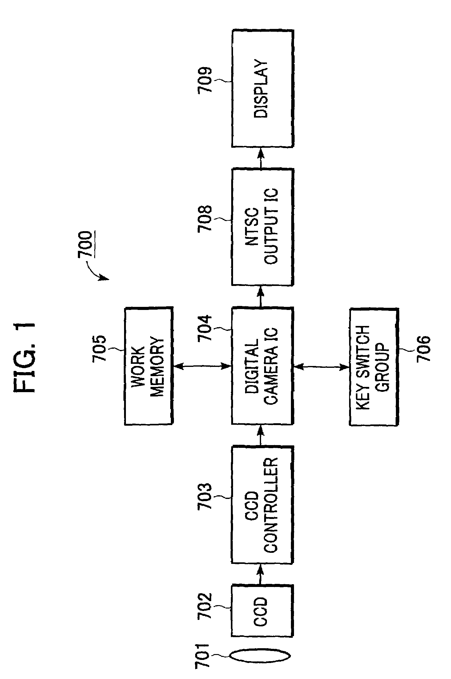
BACKGROUND OF THE INVENTION[0001]1. Field of the Invention[0002]The present invention relates to an image processing apparatus and method for efficiently compressing and encoding still images and motion pictures. More particularly, it relates to a process for efficiently compressing and encoding motion pictures by adding a simple structure to an apparatus including a general-purpose digital camera integrated circuit (IC) having a function of compressing and encoding still images.[0003]2. Description of the Related Art[0004]An image processing apparatus 700 shown in FIG. 1 is an example of known compact portable equipment with a general-purpose digital camera IC (IC having a function of compressing still images to JPEG-format images (ISO / IEC 10918)) (JPEG is an abbreviation of joint photographic experts group).[0005]Referring to FIG. 1, the image processing apparatus 700 includes a lens unit 701, a charge-coupled device (CCD) 702, a CCD control unit 703, a digital camera IC 704, a wo...

Claims


Application Information

Patent Timeline
IPC IPC(8): G06K9/36G06K9/46H04N5/907H04N5/92H04N7/50H04N101/00
CPCH04N19/42H04N19/61
Inventor ENDO, YOSHIYUKI
Owner CANON KK
Learn More