
Method and computer program product for controlling the control effectors of an aerodynamic vehicle

a technology of control effector and aerodynamic vehicle, which is applied in the direction of adaptive control, automatic actuation, instruments, etc., can solve the problems of difficult verification of the proper operation of the high complexity of failure detection and flight control reconfiguration system, and adversely affecting the ability of conventional control system to maintain, so as to achieve efficient control of the control effector and efficiently implement the

Inactive Publication Date: 2007-08-14
THE BOEING CO
View PDF21 Cites 14 Cited by
  • Summary
  • Abstract
  • Description
  • Claims
  • Application Information

AI Technical Summary

Benefits of technology

This approach provides a robust and efficient control scheme that effectively manages control effectors across all flight phases, including vertical takeoff and landing, by prioritizing thrust variations and nozzle vectoring during low velocity and aerodynamic surfaces during flight, while preventing overextension of control effector limits, ensuring stability and optimal performance.

Problems solved by technology

Unfortunately, flight control effectors may occasionally fail, thereby adversely affecting the ability of conventional control systems to maintain the dynamic stability and performance of the aerodynamic vehicle.
These failure detection and flight control reconfiguration systems are highly complex.
As such, the proper operation of these systems is difficult to verify.
Moreover, these systems introduce a risk that a flight control effector that is actually functioning properly may be falsely identified as having failed and thereafter removed from the control system, thereby potentially and unnecessarily rendering the control system less effective.
Additionally, the control effectors of an aerodynamic vehicle generally have some limitations on their performance.
Unfortunately, conventional control systems do not accommodate limitations in the range of settings and rate of change of the control effectors.
Since the control effector will be unable to make the desired change, the control system may correspondingly fail to produce the desired change in the time rate of change of the system state vector of the aircraft.
While various control systems have been developed to control the flight control effectors during flight, these control systems generally do not integrate the control provided by aerodynamic surfaces during flight with the control needed in instances in which the aircraft has no, or a negligible, velocity such that the aerodynamic control surfaces, such as the rudder, elevators, ailerons or the like, do not significantly contribute, if at all, to the lift and attitude control of the aircraft.
While generally effective, this optimization algorithm suffers from several deficiencies.
In this regard, the optimization algorithm is computationally complex, thereby requiring substantial computing resources and being difficult and costly to expand or scale to accommodate more sophisticated control schemes, such as the control scheme necessary to control vectoring nozzles as opposed to simpler bi-directional nozzles.
The computational complexity of the optimization algorithm may also cause the solution to be approximated in instances in which the optimization algorithm cannot arrive at an exact solution within the time frame required to maintain stability of the aircraft.

Method used


Image

  • Method and computer program product for controlling the control effectors of an aerodynamic vehicle
  • Method and computer program product for controlling the control effectors of an aerodynamic vehicle
  • Method and computer program product for controlling the control effectors of an aerodynamic vehicle

Examples


Embodiment Construction

[0023]The present invention now will be described more fully hereinafter with reference to the accompanying drawings, in which preferred embodiments of the invention are shown. This invention may, however, be embodied in many different forms and should not be construed as limited to the embodiments set forth herein; rather, these embodiments are provided so that this disclosure will be thorough and complete, and will fully convey the scope of the invention to those skilled in the art. Like numbers refer to like elements throughout.

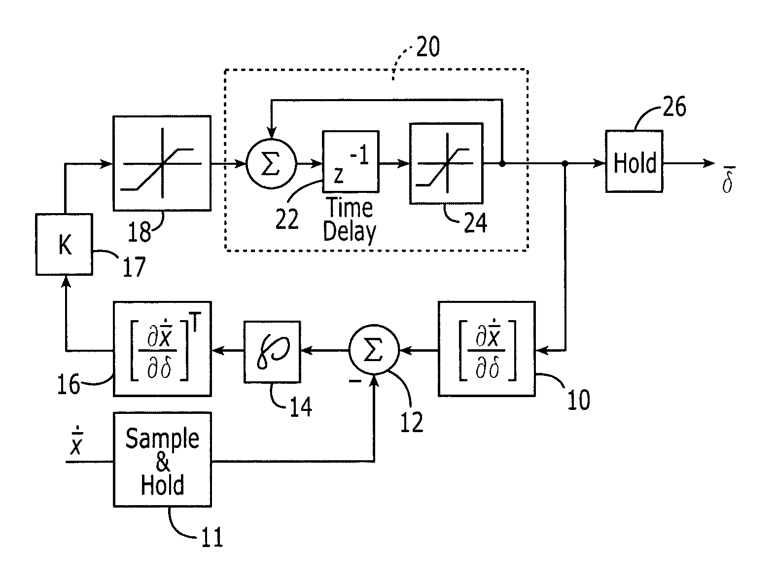
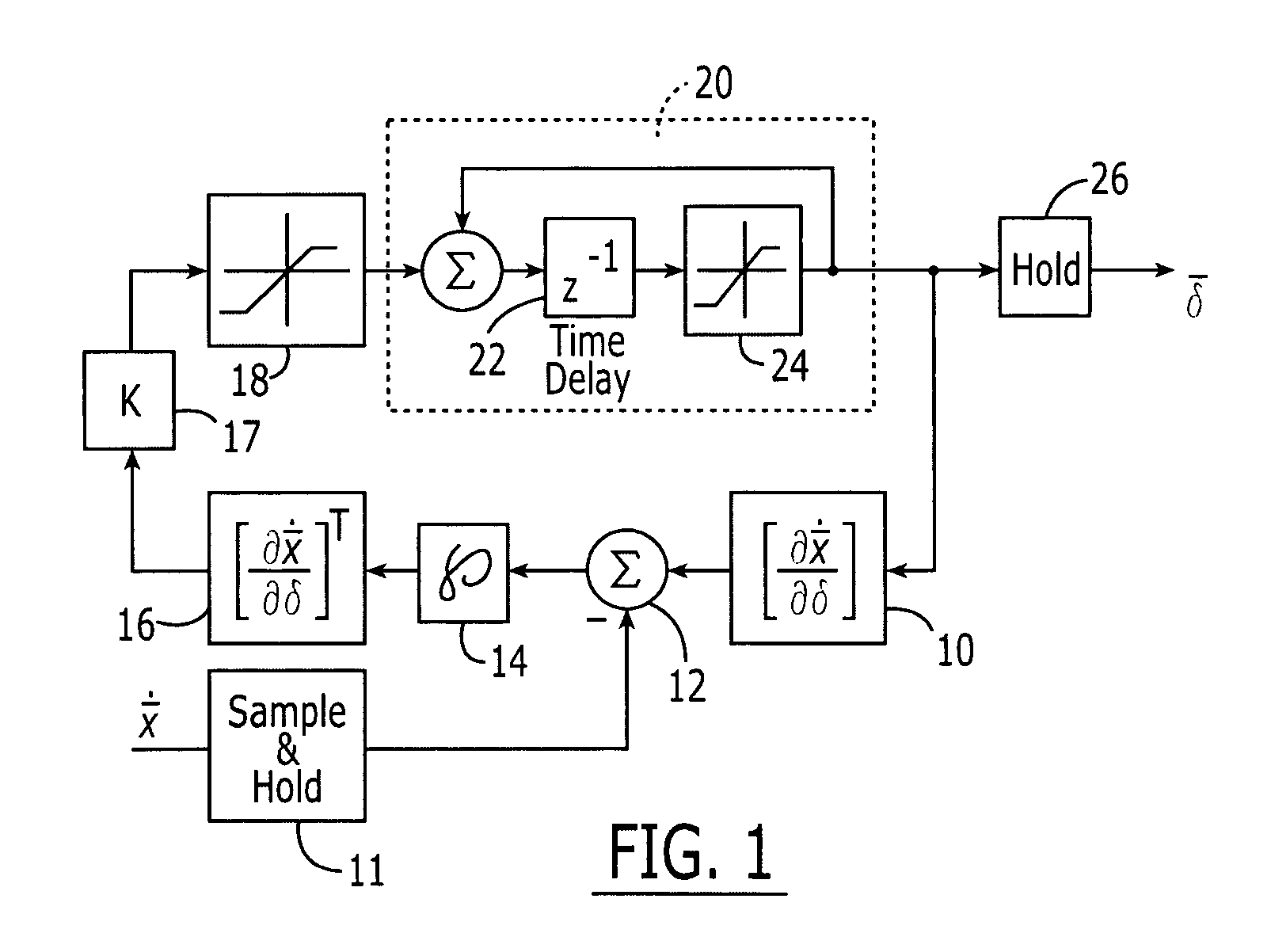
[0024]A method and a corresponding computer program product are provided for controlling the plurality of control effectors of an aerodynamic vehicle, such as an aircraft, including, for example, a direct lift aircraft capable of vertical takeoff and landing. As known to those skilled in the art, aerodynamic vehicles have a wide variety of control effectors with the type and number of control effectors depending upon the type and model of the aerodynamic v...


PUM


Abstract

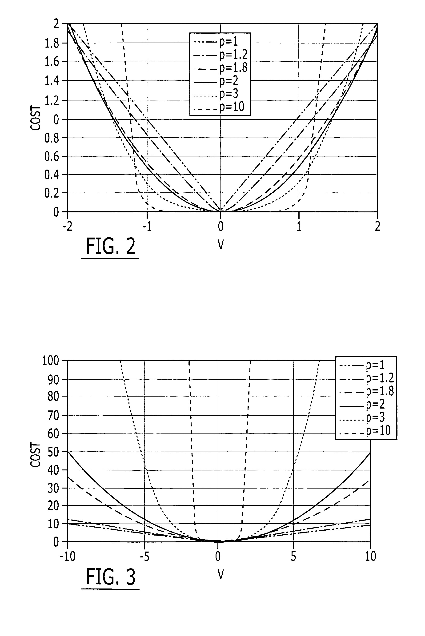
A method and computer program product are provided for controlling the control effectors of an aerodynamic vehicle including, for example, the respective positions of nozzles and aerodynamic surfaces, to affect a desired change in the time rate of change of the system state vector. The method initially determines differences between anticipated changes in the states of the aerodynamic vehicle based upon the current state of each control effector, and desired state changes. These differences may be weighted based upon a predetermined criteria, such as the importance of the respective states and / or the weight to be attributed to outliers. The differences between the anticipated and desired state changes are converted to the corresponding rates of change of the control effectors. Control signals are then issued to the control effectors to affect the desired change in the time rate of change of the system state vector.

Description

CROSS-REFERENCE TO RELATED APPLICATIONS[0001]This application is a divisional of U.S. application Ser. No. 10 / 317,370, filed Dec. 12, 2002, now U.S. Pat. No. 6,814,330, which is hereby incorporated herein in its entirety by reference.FIELD OF THE INVENTION[0002]The present invention relates generally to a method of controlling the control effectors of an aerodynamic vehicle and, more particularly, to an integrated method for controlling the control effectors of an aerodynamic vehicle, including the aerodynamic surfaces, thrust variations and nozzle vectoring, in order to efficiently cause a desired change in the time rate of change of the system state vector of the aerodynamic vehicle during various stages of flight.BACKGROUND OF THE INVENTION[0003]During flight, the control of aerodynamic vehicles, such as aircraft, is principally accomplished via a variety of flight control effectors. These flight control effectors include aerodynamic controls such as the rudder, elevators, ailero...

Claims


Application Information

Patent Timeline
Patent Type & Authority Patents(United States)
IPC IPC(8): B64C13/18G05B13/02G05D1/08
CPCG05B13/024G05D1/0825
Inventor JONES, RICHARD D.MUSGRAVE, JEFFREY L.
Owner THE BOEING CO
Learn More