
Method and apparatus for treatment of metallic workpieces

a technology for thermal treatment and workpieces, applied in lighting and heating apparatus, discharged material handling, furnace components, etc., can solve the problems of unsatisfactory economics, infrequent rejection of a number of rejects, and gas flow striking the workpiece in a diffuse and turbulent manner, and achieves high gas speed, intensive quenching, and cost-effective production.

Inactive Publication Date: 2007-08-14
IPSEN INT
View PDF7 Cites 18 Cited by
  • Summary
  • Abstract
  • Description
  • Claims
  • Application Information

AI Technical Summary

Benefits of technology

[0007]Such a method ensures that quenching gas can be used for low-distortion cooling of the workpieces when guide channels separate the individual workpieces of a charge to be cooled or the workpieces of a charge to be cooled that are placed upon each to form stacks. This results in a flow of gas in the guide channels that flows around the entire workpiece surface parallel to the axis of the workpiece and effects uniform cooling but is not affected by adjacent workpieces.
[0008]It is expedient if the guide channels, prior to the heating, are placed over the individual workpieces or the workpieces that are placed upon each other for stacking. In this manner the guide channels are subjected to the thermal treatment together with the workpieces. Even if such a measure requires guide channels made of a suitable heat-resistant material, it offers the advantage that the guide channels can be placed over workpieces that are still cold and can be used in conventional quenching chambers or the workpieces can be quenched in the thermal treatment oven.
[0009]Alternatively, the guide channels in the quenching chamber can be arranged around the individual, previously heated workpieces, or the previously heated workpieces that are placed upon each other for stacking, in order to prevent a problem when the workpieces are being heated. In this case it is especially advantageous to place the guide channels over the workpieces in the quenching chamber, for example, via an electromotor, hydraulically, or pneumatically, from one or two sides, preferably from above and / or below, so that manageable operation is ensured even when there is a limited amount of space in the quenching chamber.
[0012]It is of particular advantage if the length of the guide channels is at least equal to the height of the individual workpieces or the workpieces stacked upon each other. This channels the eddying of the quenching gas, which is unavoidable when the quenching gas strikes the workpieces, so that it does not affect the flow of gas around adjacent workpieces. In this regard, it has proven particularly effective to configure the length of the guide channels such that they project beyond the height of the individual workpieces, or of the workpieces stacked upon each other, by an amount equal to half the diameter or width of the workpieces.
[0013]In a further advantageous embodiment of the apparatus in accordance with the invention, the shape of the guide channels is cylindrical, preferably with a circular, square, or polygonal cross-section, or is adapted to the geometry of the workpieces to be cooled, in order to provide cost-effective production and furthermore in order to provide intensive quenching by means of a high gas speed caused by a narrow distance between the interior surface of the guide channels and the workpieces.
[0015]Pursuant to a further embodiment of the invention, the quenching chamber can have an inlet for the quenching gas, said inlet being adjacent to the guide channels. This offers the advantage that the flow of gas forwarded to the quenching chamber flows exclusively into the guide channels and not past the charge of workpieces or between the individual guide channels. In addition, this reduces the flow volume to a minimum. The result is that a high speed is maintained and therefore high quenching intensity is obtained. Finally suggested is that the guide channels comprise a heat-resistant material, preferably steel, iron alloys, or nickel alloys, in order to be able to place them over the workpieces even prior to providing thermal treatment to the workpieces.

Problems solved by technology

This makes possible relative movement of nozzle field and workpieces and thus ensures that the gas is applied to the workpieces in a relatively uniform manner, but it has the disadvantage that the flow of gas strikes the workpieces in a diffuse and turbulent manner.
This means that the surface of each workpiece is cooled unevenly, so that stresses occur that can lead to distortion or even fissures.
In particular with workpieces with an offset or undulating shape, or those that are projectingly stacked when a lot or charge is assembled, for example, roller bearing rings or toothed wheels, distortion is particularly noticeable and, due to the generally narrow tolerances for such workpieces, leads not infrequently to a number of rejects that is unsatisfactory in terms of economics.
It is well-known for systematically controlling the flow of gas, to provide guides with which, for example, the quenching gas can strike even those locations of the workpiece surface that would otherwise be located in the shadows of the flow; however, such a measure is not satisfactory because, in addition to the relatively high degree of complexity associated with arranging the guides to correspond to the workpiece geometry, the guides do not prevent eddies from occurring when the flow of gas strikes the workpieces, which can have a negative effect on how adjacent workpieces in a charge cool and can thus cause distortion.

Method used


Image

  • Method and apparatus for treatment of metallic workpieces
  • Method and apparatus for treatment of metallic workpieces
  • Method and apparatus for treatment of metallic workpieces

Examples


Embodiment Construction

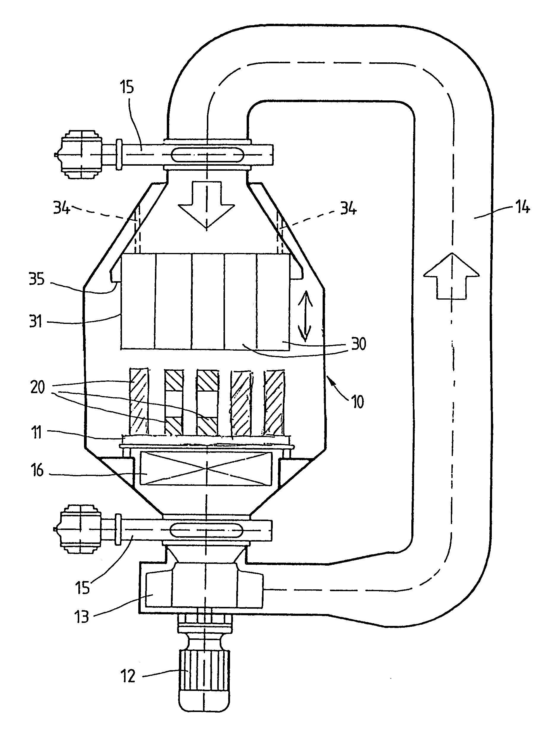
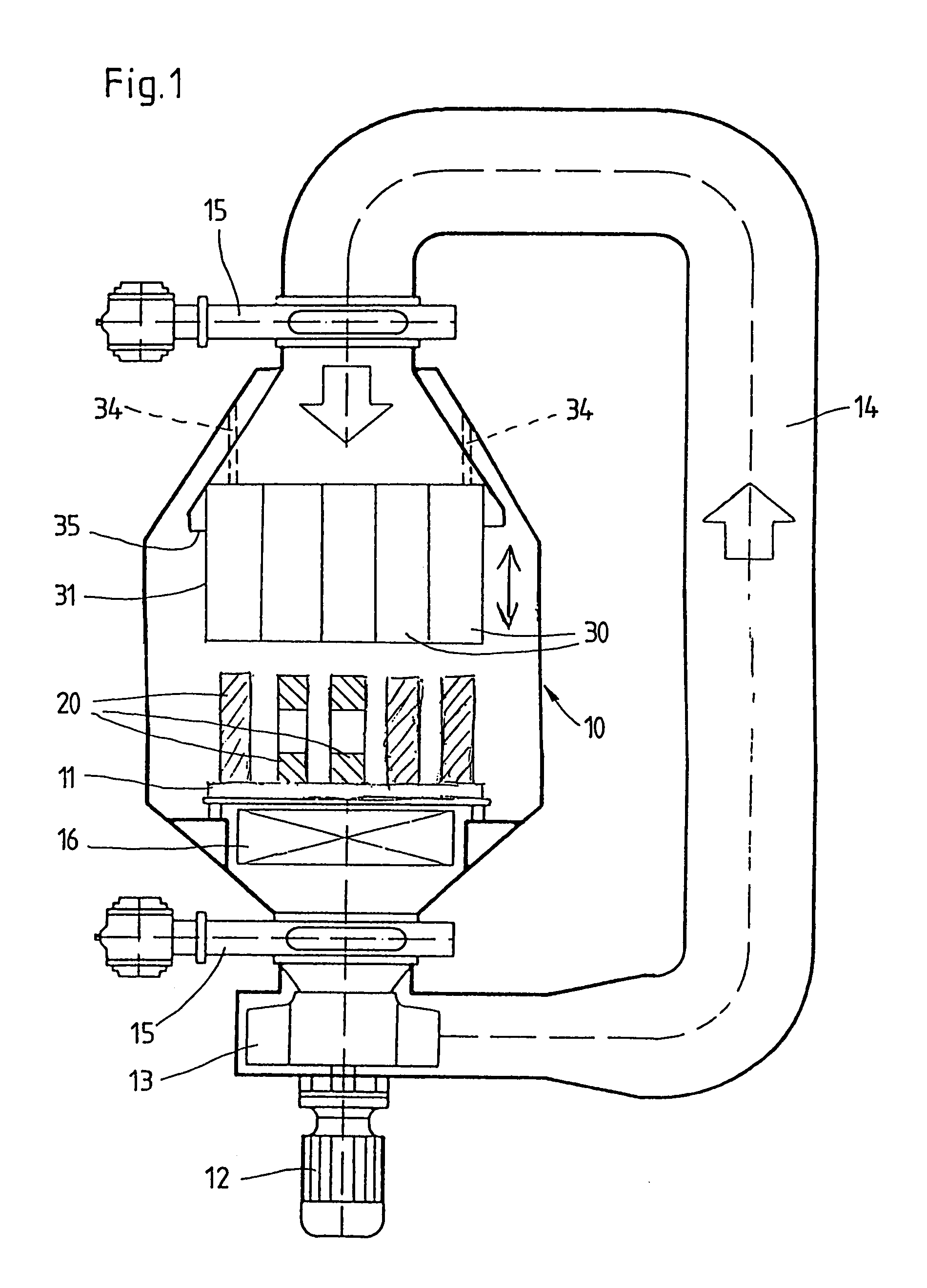
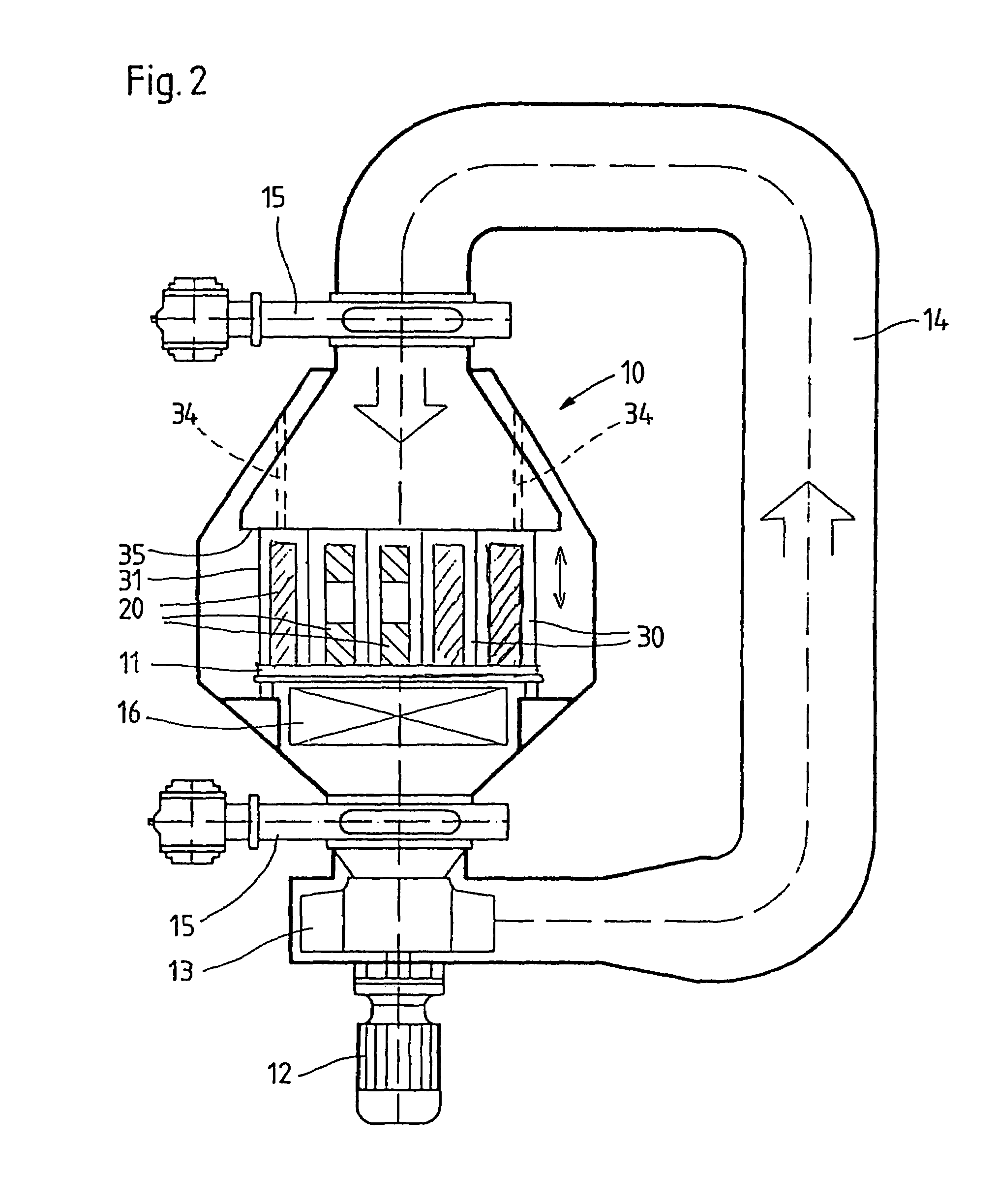
[0023]The quenching chamber 10 illustrated in FIGS. 1 and 2 is part of an apparatus for the thermal treatment of metallic workpieces 20 and is arranged, for example, at the end of a roller hearth-type furnace. The quenching chamber 10 can be embodied such that it can be operated either with a vacuum or at atmospheric pressure or at overpressure. Located in the quenching chamber 10 is a grate or grid 11 carrying workpieces 20 that have been heated and are to be cooled; the grate makes it possible for a quenching gas to circulate vertically in the quenching chamber 10. For circulating the quenching gas, a fan 13 driven by a motor 12 is arranged below the grate 11. Outside of the quenching chamber 10, the quenching gas is conducted through a gas channel 14 in the direction of flow indicated by the arrow in FIGS. 1 and 2. Furthermore provided above and below the quenching chamber 10 are flaps or the like 15 that prevent the quenching gas from circulating until the fan 13 has achieved th...


PUM

PropertyMeasurementUnit
Lengthaaaaaaaaaa
Flow rateaaaaaaaaaa
Diameteraaaaaaaaaa

Abstract

A method and an apparatus for the thermal treatment of metallic workpieces with which gas quenching can be obtained that is low in distortion, even for workpieces with an undulating shape or workpieces that are projectingly stackable are provided. In accordance with the method, after being heated the workpieces are cooled in a quenching chamber with a quenching gas, whereby the quenching gas is intentionally caused to flow around the workpieces by means of guide channels that have a closed lateral surface and that enclose the workpieces along the direction of flow of the quenching gas. The apparatus comprises a quenching chamber in which the workpieces can be cooled with a quenching gas, and wherein guide channels are provided to ensure that the quenching gas flows around the workpieces, the guide channels having a closed lateral surface and enclosing the workpieces along the direction of flow of the quenching gas.

Description

BACKGROUND OF THE INVENTION[0001]The present invention relates to a method for the thermal treatment of metallic workpieces, in particular workpieces with an overset or undulating shape or workpieces that are projectingly stackable, in which method the workpieces, after being heated, are cooled in a quenching chamber with a quenching gas. The present invention furthermore relates to an apparatus with which such a method can be performed.[0002]Metallic workpieces undergo thermal treatment in order to produce defined workpiece properties, for example, a high degree of hardness or sufficient resistance to wear. The result of the thermal treatment is a change in the structure of the workpiece, for example, a conversion of the cubic, surface-centered γ-structure of carbon-rich austenite plates into the cubic space-centered α-structure of ferrite plates. In addition to temperature and original structure, particularly important in terms of the results of the treatment are the speed at whic...

Claims


Application Information

Patent Timeline
IPC IPC(8): C21D1/62C21D1/767C21D1/613
CPCC21D1/62C21D1/767C21D1/613
Inventor PETER, WOLFGANGEDENHOFER, BERNDBOUWMAN, JAN-WILLEM
Owner IPSEN INT
Features
  • Generate Ideas
  • Intellectual Property
  • Life Sciences
  • Materials
  • Tech Scout
  • Unparalleled Data Quality
  • Higher Quality Content
  • 60% Fewer Hallucinations
Learn More