
Magnetic tape

a technology of magnetic tape and tape, which is applied in the direction of maintaining head carrier alignment, track following alignment, instruments, etc., can solve the problems of reducing the data recording area, the increase in recording capacity achieved by this approach is of necessity limited, and the tape length cannot be extended to achieve the effect of increasing the recording capacity

Inactive Publication Date: 2007-08-14
QUANTUM CORP
View PDF106 Cites 110 Cited by
  • Summary
  • Abstract
  • Description
  • Claims
  • Application Information

AI Technical Summary

Benefits of technology

[0006]Accordingly, an object of the present invention is to provide magnetic tape which is capable of servo tracking without reducing the data area.
[0008]Still another object of the present invention is to provide magnetic tape having a high recording capacity.
[0009]As a result of extensive investigation, the inventors of the present invention have found that magnetic tape accomplishing the above objects can be obtained by incorporating specific fine particles into the backcoating layer of the magnetic tape and forming specific voids in the backcoating layer to make the backcoating layer capable of forming servo tracks.

Problems solved by technology

Since the tape length that can be put in a tape cartridge as wound is the upper limit of the recording capacity, extension of the tape length for increasing the recording capacity cannot be achieved but by reducing the tape thickness.
Therefore, an increase in recording capacity attained by this approach is of necessity limited.
Like this, conventional servo tracking systems use the same side of magnetic tape as used for data recording, which results in reduction of the data recording area.

Method used

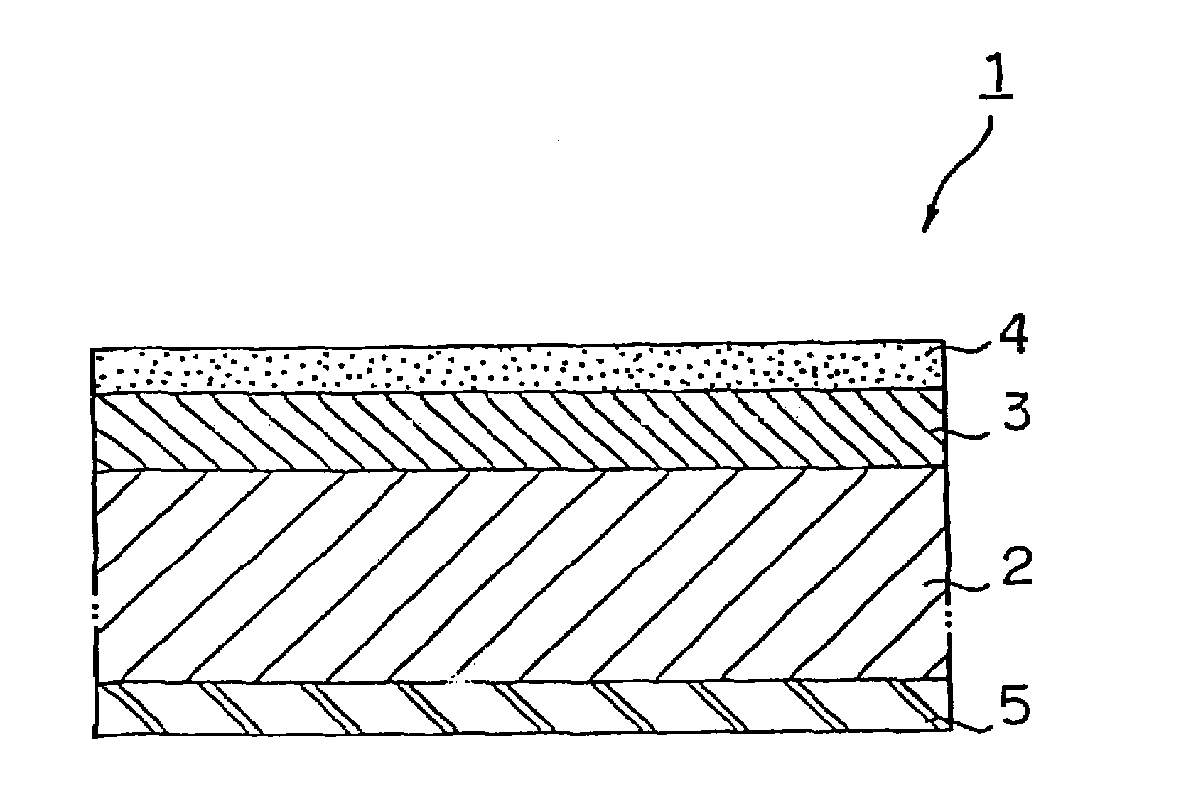
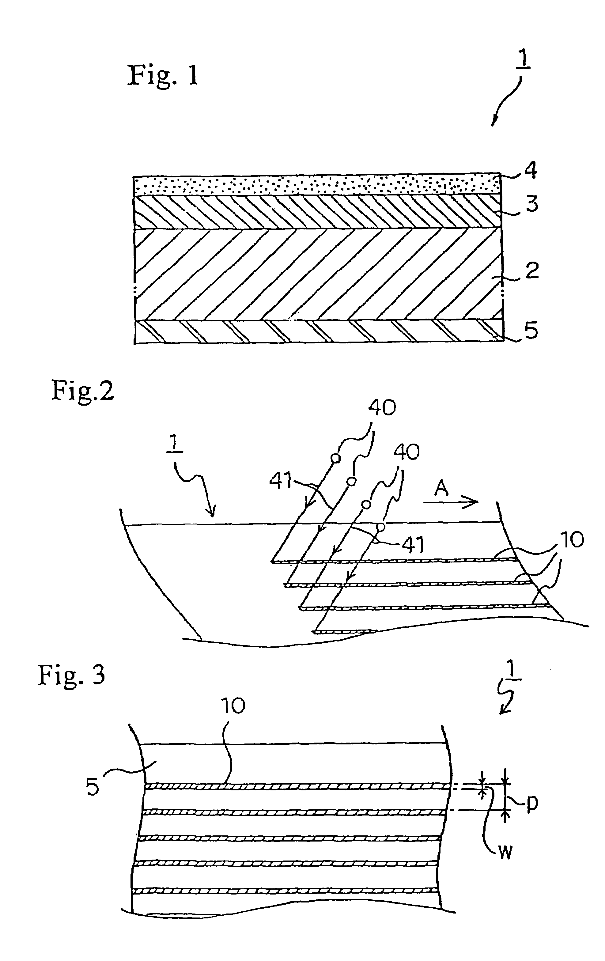
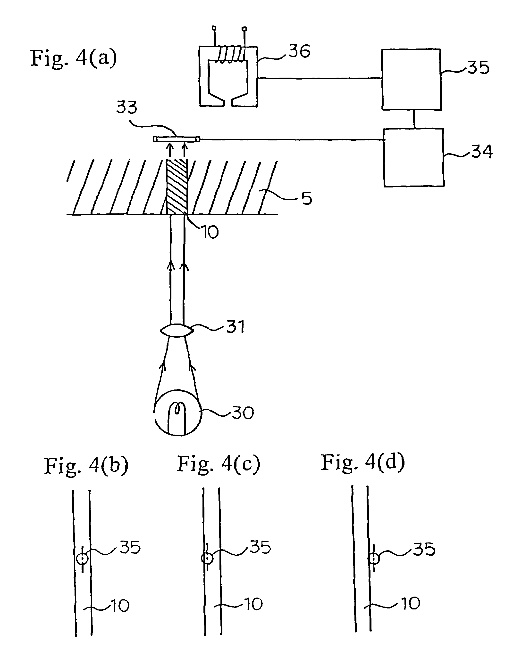

Image

  • Magnetic tape
  • Magnetic tape
  • Magnetic tape

Examples


example 1

[0117]The following components except the hardener were kneaded in a kneader, dispersed in a stirrer, and further finely dispersed in a sand mill. The dispersion was filtered through a 1 μm filter, and finally, the hardener was added thereto to prepare a backcoating composition, a magnetic coating composition, and an intermediate layer coating composition having the respective formulations described below.

[0118]

Formulation of Backcoating Composition:FeOx  70 parts(primary particle size: 32 nm; BET specificsurface area: 52 m2 / g;coercive force: 10.3 kA / m (129 Oe); saturation magnetization:85 Am2 / kg; divalent Fe content: 19.7%; x = 1.363)Phosphoric ester (lubricant)  2 parts(Phosphanol RE610 (trade name), producedby Toho Chemical Industry Co., Ltd.)Carbon black  1 part(primary particle size: 54 nm; BET specific surfacearea: 32 m2 / g;DBP oil absorption: 180 cm3 / 100 g)Indium-doped tin oxide (ITO)  30 parts(primary particle size: 35 nm)Polyurethane resin (binder)  17 parts(number average m...

example 2

[0121]A magnetic tape was obtained in the same manner as in Example 1, except for using carbon black having a primary particle size of 28 nm, a BET specific surface area of 70 m2 / g, and a DBP oil absorption of 50 cm3 / 100 g as the carbon black in the backcoating composition used in Example 1. A color change pattern was formed on the backcoating layer of the magnetic tape in the same manner as in Example 1.

example 3

[0122]A magnetic tape was obtained in the same manner as in Example 1, except that the amount of the FeOx of the backcoating composition used in Example 1 was changed to 100 parts and that ITO was not incorporated. A color change pattern was formed on the backcoating layer of the magnetic tape in the same manner as in Example 1.


PUM

PropertyMeasurementUnit
particle sizeaaaaaaaaaa
mean roughness Rzaaaaaaaaaa
arithmetic mean roughness Raaaaaaaaaaa

Abstract

A magnetic tape (1) characterized by having a backcoating layer (5) which comprises a binder and fine particles having been dispersed in the binder and being capable of irreversibly changing in color on oxidation reaction, and has a sufficient number of microvoids of sufficient size to supply sufficient oxygen to cause the oxidation reaction.

Description

[0001]This application is a continuation and claims the benefit of priority under 35 USC 120 of U.S. application Ser. No. 10 / 341,739, filed Jan. 14, 2003, now abandoned, U.S. application Ser. No. 10 / 170,830, filed Jun. 13, 2002, now abandoned, and U.S. application Ser. No. 09 / 530,005, filed Jul. 21, 2000, now abandoned. In addition, this application claims the benefit of priority under 35 U.S.C. 119 of: 371 PCT / JP98 / 04767, filed Oct. 21, 1998, which claims the benefit of Japanese Application Number 9-289885, filed Oct. 22, 1997.TECHNICAL FIELD[0002]The present invention relates to magnetic tape having optical servo tracks. More particularly, it relates to magnetic tape having optical servo tracks on the side opposite to the magnetic recording side.BACKGROUND ART[0003]The recent expanding scale of the computer network and the importance of security for data management have been increasing the demand for magnetic tape having an increased recording capacity for use as a medium for data...

Claims


Application Information

Patent Timeline
Patent Type & Authority Patents(United States)
IPC IPC(8): G11B5/735B32B5/16G11B5/70
CPCG11B5/584G11B5/735G11B5/714Y10T428/256Y10T428/257Y10T428/24355G11B5/7356G11B5/7358
Inventor ISHIKAWA, AKIRAISHII, TAKASHIKATASHIMA, MITSUHIROHOSOYA, MANABUONDA, TOMOHIKO
Owner QUANTUM CORP
Learn More