
Method and apparatus for high voltage gain using a magnetostrictive-piezoelectric composite

a composite and magnetostrictive technology, applied in piezoelectric/electrostrictive/magnetostrictive devices, piezoelectric/electrostriction/magnetostriction machines, electrical apparatus, etc., can solve the problem of low coupling magnitude for both connectivities in prior art investigations, no single phase material with high inherent coupling between spin and polarization has yet to be found, etc. problem, to achieve the effect of high voltage gain

Inactive Publication Date: 2007-08-14
VIRGINIA TECH INTPROP INC
View PDF4 Cites 20 Cited by
  • Summary
  • Abstract
  • Description
  • Claims
  • Application Information

AI Technical Summary

Problems solved by technology

However, to date no single phase material with a high inherent coupling between spin and polarization has yet to be found.
However, the magnitude of the coupling was low for both connectivities in these prior art investigations.
However, there were no reports about power device applications of the resonance ME effect.
Such applications require high voltage gains and high output efficiencies.
However, lack of good magneto-electric materials has hampered high power applications.

Method used


Image

  • Method and apparatus for high voltage gain using a magnetostrictive-piezoelectric composite
  • Method and apparatus for high voltage gain using a magnetostrictive-piezoelectric composite
  • Method and apparatus for high voltage gain using a magnetostrictive-piezoelectric composite

Examples


Embodiment Construction

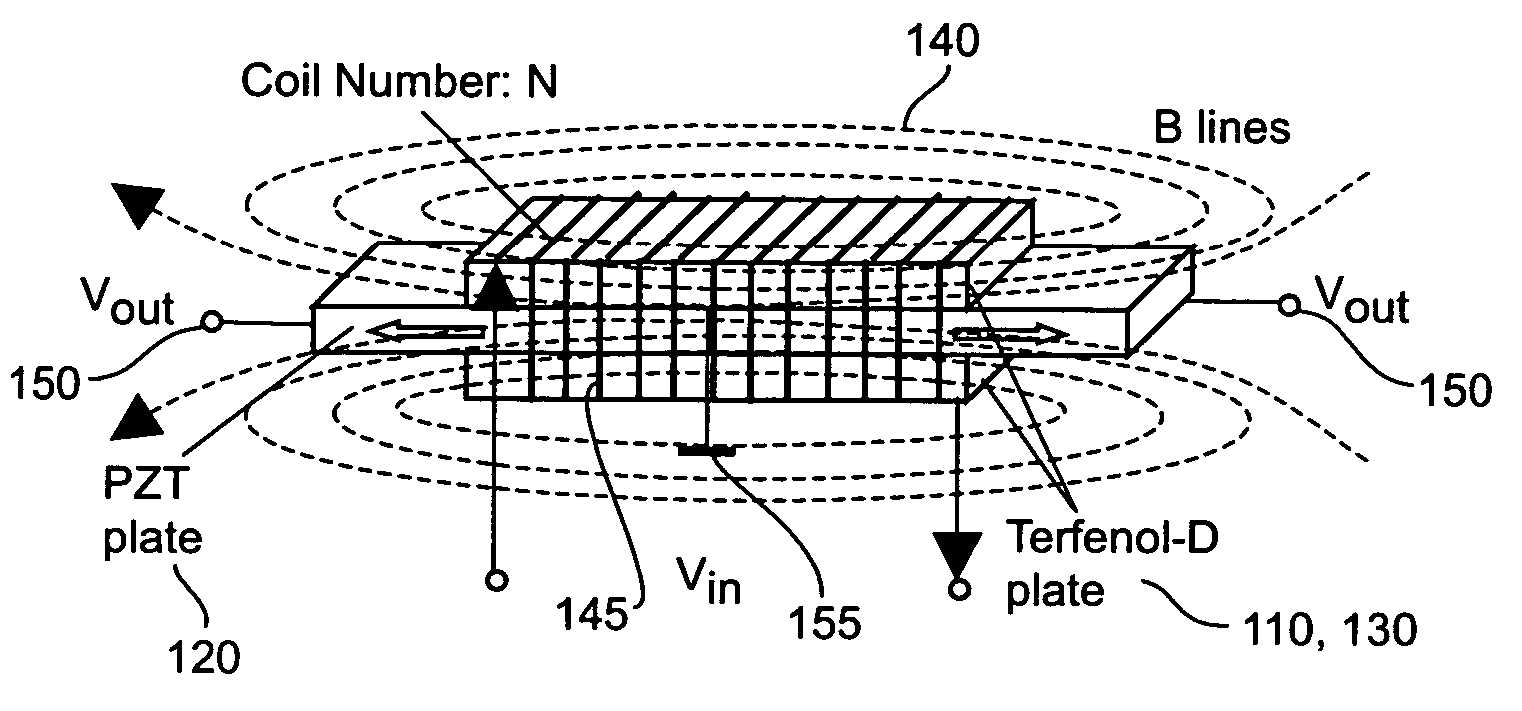
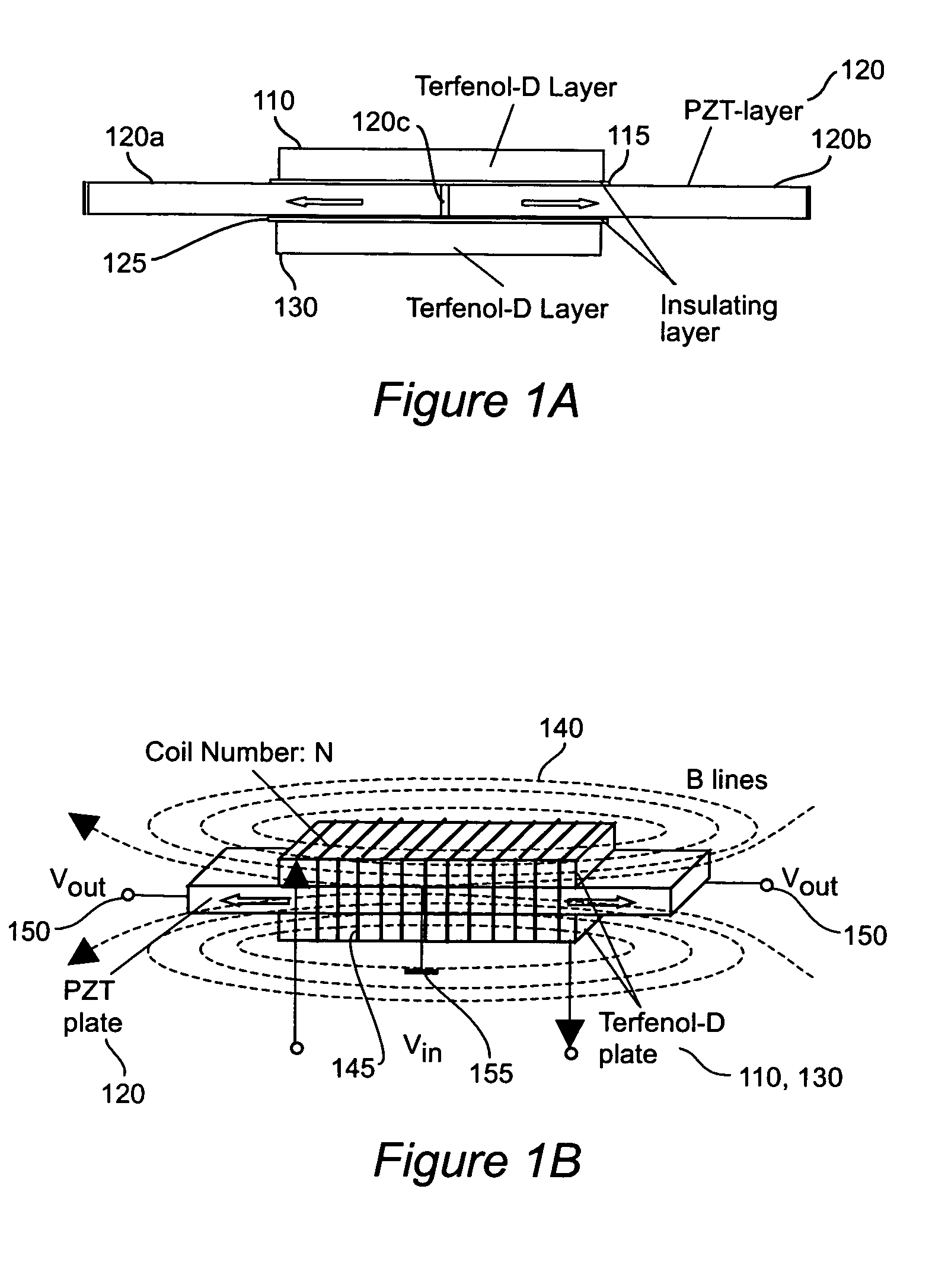
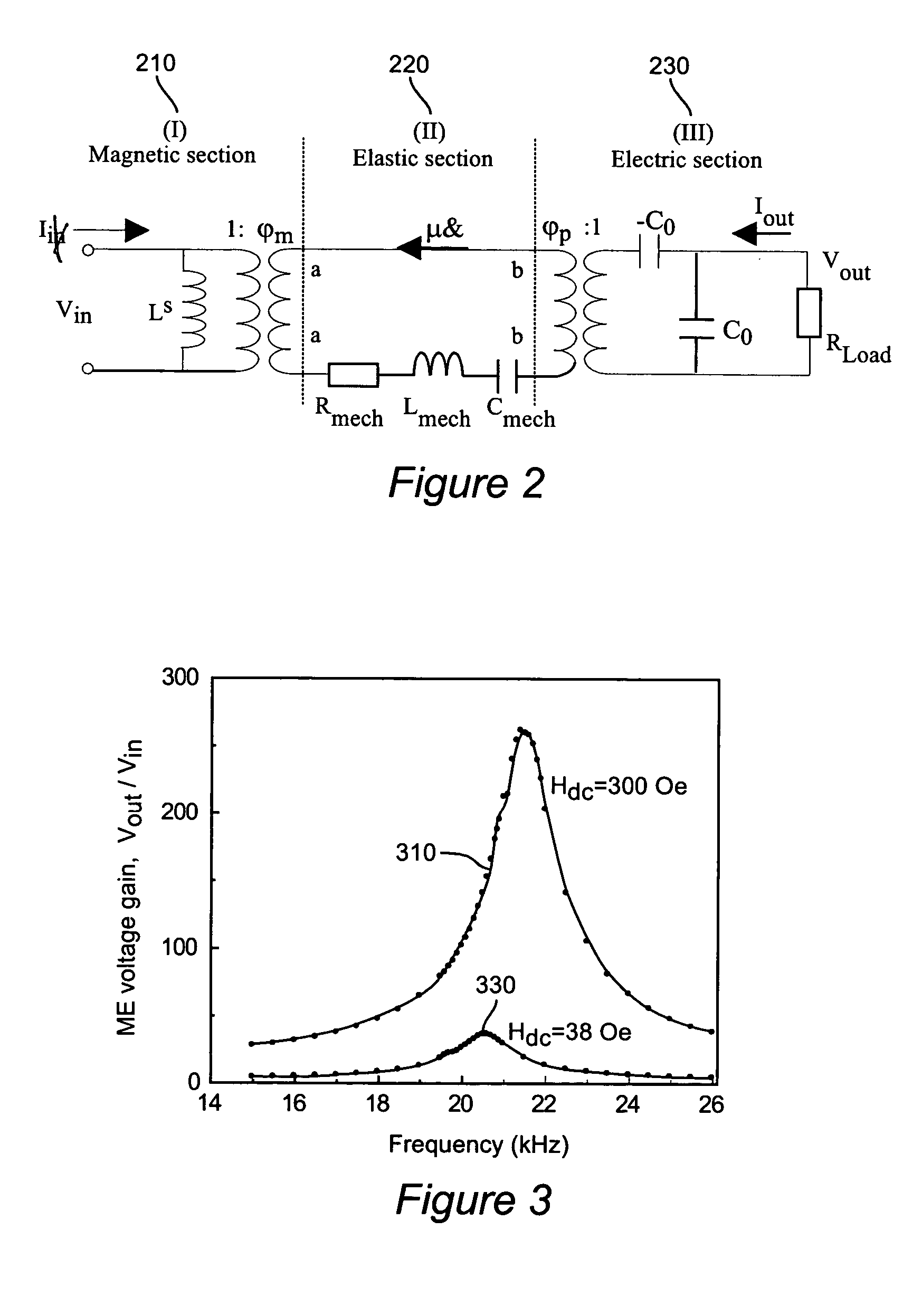
[0019]Referring now to the drawings, and more particularly to FIG. 1a, there is shown the composite geometry for the best mode of implementation of the invention. It is a long plate type piezoelectric / magnetostrictive laminate composite, in which the piezoelectric layer 120 is sandwiched between two magnetostrictive layers 110 and 130, which are electrically insulated from each other by thin electric insulators 115 and 125, such as thin Al2O3 or thin glass. More complicated multilayer geometries of this general type are possible, but that given in FIG. 1a readily allows for equivalent circuit analysis. The conductive magnetostrictive layers 110 and 130 are separated by insulating thin layers 115 and 125, and thus eddy currents are effectively eliminated if the thickness of the magnetostrictive layers 110 and 130 are sufficiently thin. This magneto-electric laminate design differs from previous ones, as its aspect ratio is high, favoring the longitudinal direction along which fields ...


PUM


Abstract

A method and apparatus attains high voltage gain by using a composite structure of an elastic section of piezoelectric layers bonded between magnetic and electric sections of magnetostrictive layers, with a harmonic magnetic field being applied along the layers at a mechanical resonance frequency of the composite structure, through coils around the laminate carrying current, such as to produce a continuity of both magnetic and electric flux lines, and achieving a high voltage output.

Description

[0001]This application claims the benefit of Provisional Application No. 60 / 550,732 entitled New Magneto-Electric Transformer with Higher Voltage Gain filed on Mar. 8, 2004. The invention was made under partial support of grant numbers N000140210340, N000140210126, and MURI N000140110761 from the Office of Naval Research.BACKGROUND OF THE INVENTION[0002]1. Field of the Invention[0003]The present invention generally relates to high voltage miniature transformers and more particularly to use of magneto-electric (ME) laminate composites in such transformers.[0004]2. Background Description[0005]The magneto-electric effect is a polarization response to an applied magnetic field H, or conversely a spin response to an applied electric field E. Ferro-electromagnetic materials have been studied, such as BiFeO3 and Pb(Fe1 / 2Nb1 / 2)O3. However, to date no single phase material with a high inherent coupling between spin and polarization has yet to be found.[0006]Magneto-electric behavior has also...

Claims


Application Information

Patent Timeline
Patent Type & Authority Patents(United States)
IPC IPC(8): H01L41/08H01L41/00
CPCH01L41/00H10N35/00H10N30/00
Inventor VIEHLAND, DWIGHT DOUGLASDONG, SHUXIANGLI, JIEFANG
Owner VIRGINIA TECH INTPROP INC
Learn More