Optical system for ultraviolet light

an optical system and ultraviolet light technology, applied in the field of optical systems for ultraviolet light, can solve the problems of chromatic aberration, difficult to provide purely refractive systems with sufficient correction of color errors, and insufficient material availability for producing transparent optical elements, etc., to achieve high numerical aperture, effective numerical aperture, and high refractive index

Active Publication Date: 2007-08-14
CARL ZEISS SMT GMBH
View PDF13 Cites 43 Cited by
  • Summary
  • Abstract
  • Description
  • Claims
  • Application Information

AI Technical Summary

Benefits of technology

[0018]It is one object of the invention to provide an optical system for ultraviolet light having wavelengths of λ≦200 nm which, in comparison with conventional optical systems for this wavelength range, has more degrees of freedom for the optical design, and in particular more degrees of freedom for the optical correction. It is another object to provide an optical system that is suitable as a projection objective for a microlithography projection exposure apparatus and which permits high numerical apertures which, with the use of an immersion liquid having a high refractive index, also enable effective numerical apertures NA>1 for image generation.
[0025]The use of a liquid transparent to the useful light in the interspace makes it possible to considerably extend the spectrum of the materials available for forming transparent optical components. The restriction to a small number of suitably transparent solids with their fixedly predetermined optical properties in particular with regard to refractive index and dispersion is eliminated. An improved color correction that is thereby possible with the aid of refractive components can open up new degrees of design freedom elsewhere in the optical system since these system parts can at least partly be relieved of the burden of color correction tasks. Within a liquid lens group, moreover, with the use of liquids whose refractive index is significantly closer to the refractive index of the adjacent solid lenses and to the refractive index of gases, significantly smaller index jumps occur at the solid-liquid interfaces, so that the individual optical elements can have generous position tolerances despite high angles of incidence even in the case of greatly curved interfaces. This permits more relaxed beam guidance and it is possible to achieve a reduced sensitivity of the optical system toward misalignment.
[0027]In one development, the liquid has, at an operating wavelength of the optical system, a dispersion DL greater than the dispersion DS of the highest dispersive solid material used for the optical elements at the operating wavelength, and the interspace has the form of a negative lens. As a result, it is possible with the aid of the liquid to provide a highly dispersive diverging lens which, in interaction with at least one positive lens made of a solid material having less wavelength dependence of its refractive index, enables an effective color correction in particular of the chromatic longitudinal aberration CHL. The term “dispersion” here designates the refractive dispersion dn / dλ describing the wavelength dependence of the refractive index of a transparent material. The dispersion DL may in particular be higher than that of synthetic quartz. In the case of a negative liquid lens, the axial extent of the interspace increases from the optical axis toward the edge, so that the center thickness is less than the edge thickness, a biconcave interspace preferably being formed.
[0028]It is also possible for the liquid to have, at an operating wavelength of the optical system, a dispersion DL less than the dispersion of the least refractive solid material used for the optical elements. The dispersion DL may in particular be less than that of calcium fluoride. In this case, it is expedient if the liquid lens has the form of a positive lens. In particular, the interspace may be formed in biconvex fashion. As a result, it is possible with the aid of the liquid to provide a low-dispersive positive lens which, in interaction with at least one adjacent negative lens made of a solid material with greater dispersion, enables an effective color correction.
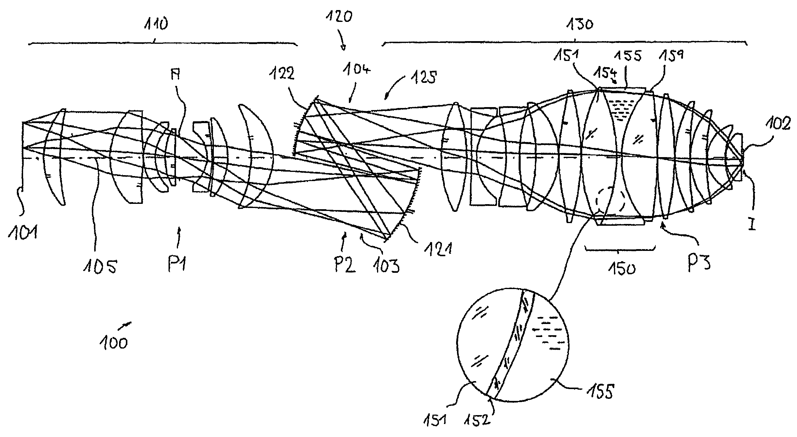
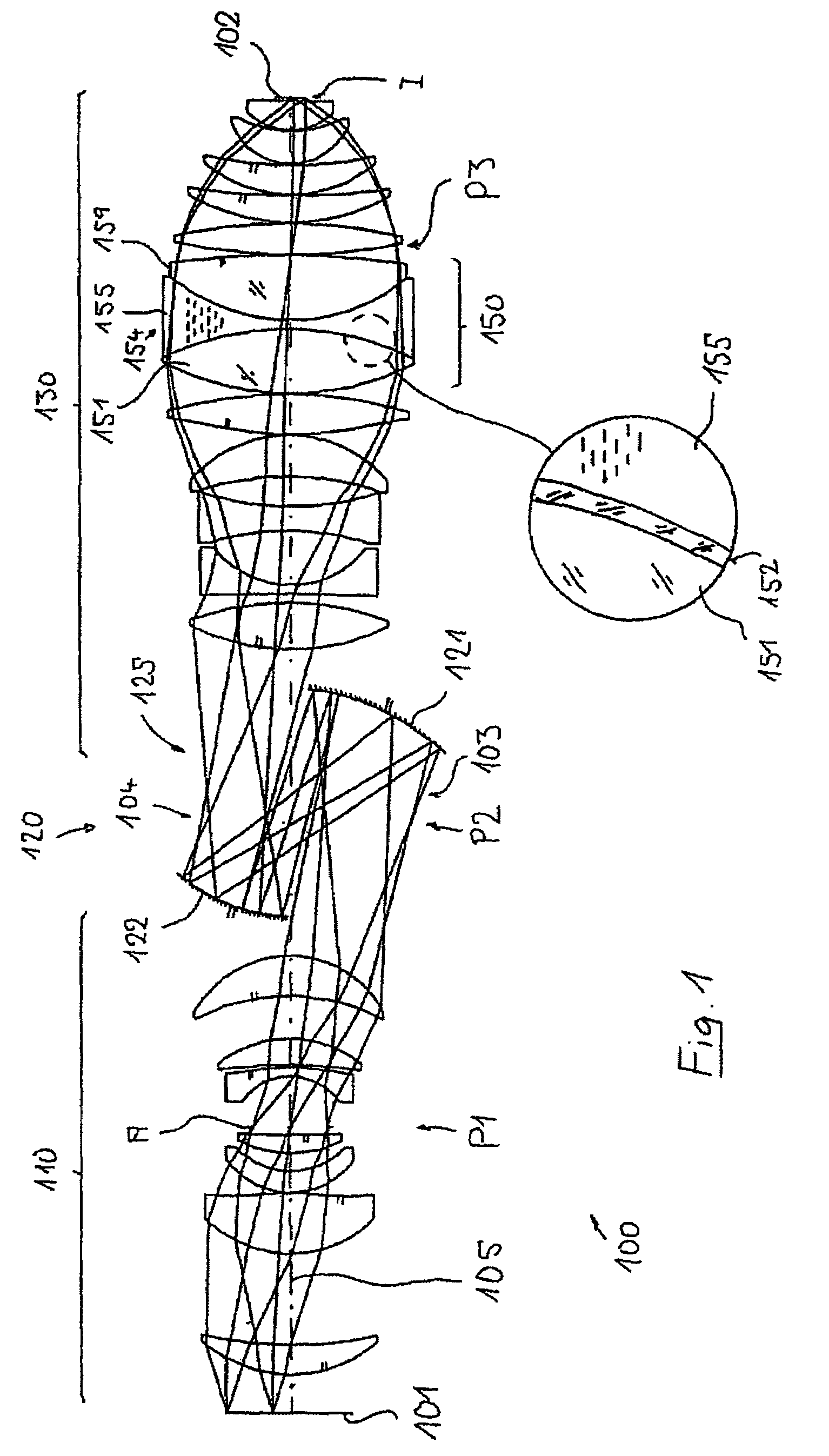
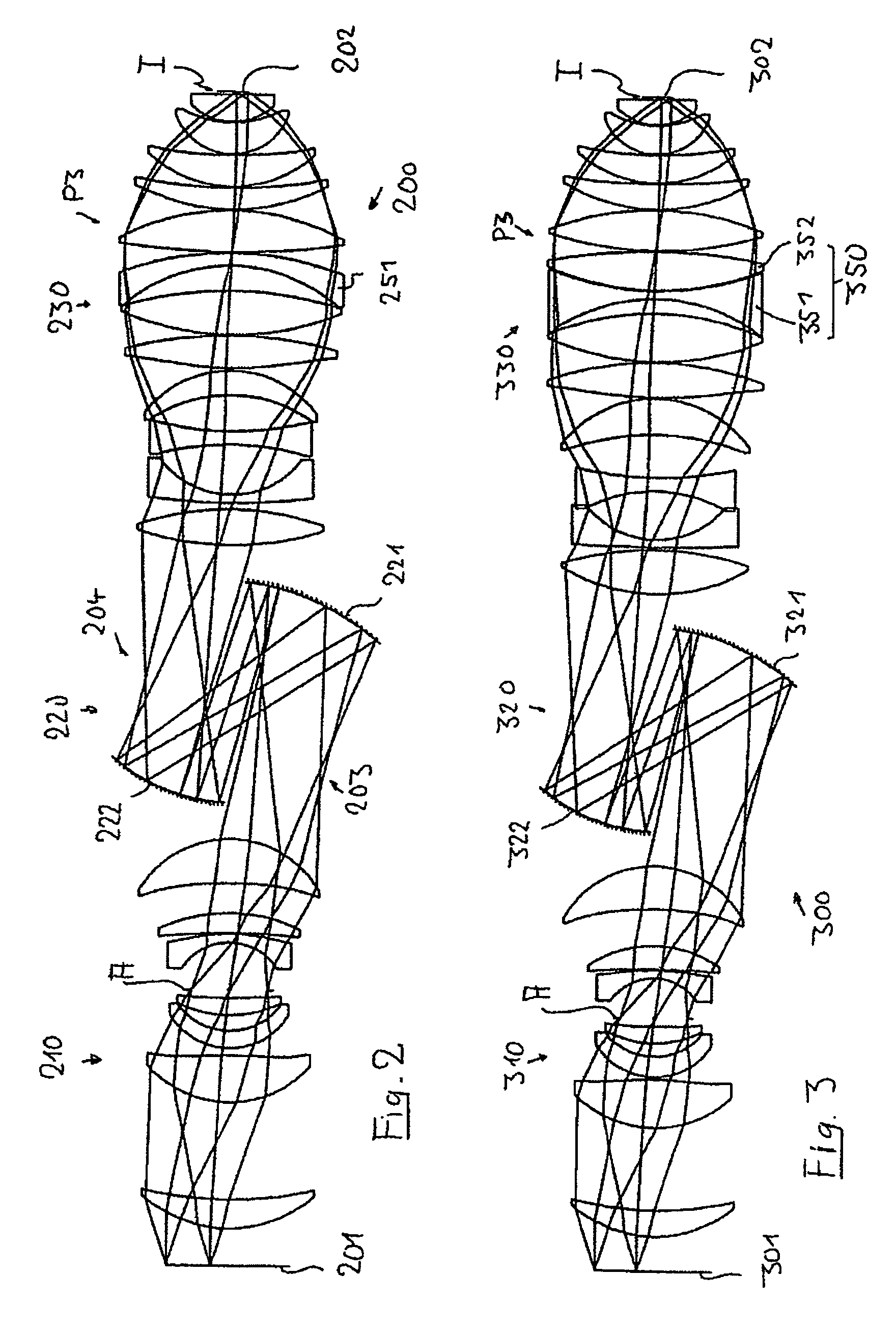
[0029]Preferred optical systems are designed as imaging systems for imaging a pattern arranged in a first surface into a second surface, which is optically conjugated with respect to the first surface. In the case of projection objectives for microlithography, a mask (reticle) may be arranged in the first surface (object surface) and a wafer to be exposed may be arranged in the second surface (image surface). The optical system may be designed in such a way that a direct imaging is effected without an intermediate image. It is also possible for one or more intermediate images to be generated between the first and second surfaces, said intermediate images lying in the region of further field surfaces of the system. Pupil surfaces of the imaging lie between the field surfaces. In preferred embodiments, the interspace or the liquid lens is arranged in a region of the optical system that is near the pupil. The liquid lens thus lies at least partly in a pupil surface or in optical proximity thereto. A “region that is near the pupil” in this sense is distinguished in particular by the fact that, in the region which is near the pupil, the marginal ray height of the imaging is larger than the principal ray height. Preferably, the marginal ray height in the region of the liquid lens is at least twice as large as the principal ray height. A negative lens in the region of large marginal ray heights may contribute particularly effectively to the color correction, in particular to the correction of the chromatic longitudinal aberration CHL.

Problems solved by technology

For very small resolutions, however, it is necessary in this case to work with numerical apertures NA of more than 0.8 or 0.9, which can be realized only with difficulty in dry systems with a sufficiently large working distance on the image side.
At wavelengths λ≦200 nm, however, there are only few sufficiently transparent materials available for producing the transparent optical elements.
However, since the Abbe constants of these materials are relatively close together, it becomes more and more difficult to provide purely refractive systems having sufficient correction of color errors (chromatic aberrations).
The conventional design approaches cannot achieve this object or can achieve it only with disproportionately high outlay.
Refractive systems require a material deployment that increases exponentially with the aperture, and also aspheric forms that are difficult to manufacture.
The catadioptric systems with folding mirrors for beam splitting often have structural space problems and a high material deployment may likewise be necessary.
It has been shown that such advantageous systems are comparatively difficult to correct chromatically.

Method used


Image

  • Optical system for ultraviolet light
  • Optical system for ultraviolet light
  • Optical system for ultraviolet light

Examples


Embodiment Construction

[0049]The invention is explained below on the basis of exemplary embodiments in which optical imaging systems are optimized in the form of projection objectives for microlithography in accordance with the invention.

[0050]FIG. 1 shows an embodiment of a catadioptric projection objective 100 designed as an immersion objective for an operating wavelength of approximately 193 nm. It is provided for imaging a pattern of a mask arranged in its object plane 101 onto its image plane 102 oriented parallel to the object plane, on a reduced scale, for example on a scale of 4:1. In this case, precisely two real intermediate images 103, 104 are generated between object plane and image plane. A first, purely refractive (dioptric) objective part 110 is designed in such a way that the pattern of the object plane is imaged into the first intermediate image 103 on a magnifying scale. A second, purely reflective (catoptric) objective part 120 images the first intermediate image 103 into the second int...


PUM


Abstract

An optical system for ultraviolet light having wavelengths λ≦200 nm, which may be designed in particular as a catadioptric projection objective for microlithography, has a plurality of optical elements including optical elements made of synthetic quartz glass or a fluoride crystal material transparent to a wavelength λ≦200 nm. At least two of the optical elements are utilized for forming at least one liquid lens group including a first delimiting optical element, a second delimiting optical element, and a liquid lens, which is arranged in an interspace between the first delimiting optical element and the second delimiting optical element and contains a liquid transparent to ultraviolet light having wavelengths λ≦200 nm. This enables effective correction of chromatic aberrations even in the case of systems that are difficult to correct chromatically.

Description

[0001]This application claims benefit from U.S. provisional application No. 60 / 619,698 filed on Oct. 19, 2004, the disclosure of which is incorporated herein by reference.BACKGROUND OF THE INVENTION[0002]1. Field of the Invention[0003]The invention relates to an optical system for ultraviolet light having wavelengths λ≦200 nm. A preferred field of application is projection objectives for microlithography.[0004]2. Description of the Related Art[0005]Optical systems that can be used in the deep ultraviolet range (DUV) at wavelengths λ≦200 nm are required for example in microlithography projection exposure apparatuses for the fabrication of semiconductor components and other finely patterned devices. They may be provided as projection objectives for projecting patterns of photomasks or reticles, which are referred to generally hereinafter as masks or reticles, onto a light-sensitive object, in particular a semiconductor wafer coated with a light-sensitive layer, with a high resolution ...

Claims


Application Information

Patent Timeline
Patent Type & Authority Patents(United States)
IPC IPC(8): G02B13/14G02B1/06
CPCG02B3/12G02B3/14G02B13/143G02B17/0812G02B17/0892
Inventor EPPLE, ALEXANDERGRUNER, TORALFSINGER, WOLFGANG
Owner CARL ZEISS SMT GMBH
Why Eureka
Try Eureka