Method and apparatus for X-ray reflectance measurement

a technology of x-ray reflectance and measurement method, which is applied in the direction of instruments, material analysis using wave/particle radiation, nuclear engineering, etc., can solve the problems of inferior repeatability of x-ray reflectance method thickness, inaccurate determination of incident angle, and inability to observe thickness determined by current x-ray reflectance method, etc., to achieve improved repeatability in determining incident angle, improved accuracy, and high accuracy

Inactive Publication Date: 2007-08-14
RIGAKU CORP
View PDF12 Cites 15 Cited by
  • Summary
  • Abstract
  • Description
  • Claims
  • Application Information

AI Technical Summary

Benefits of technology

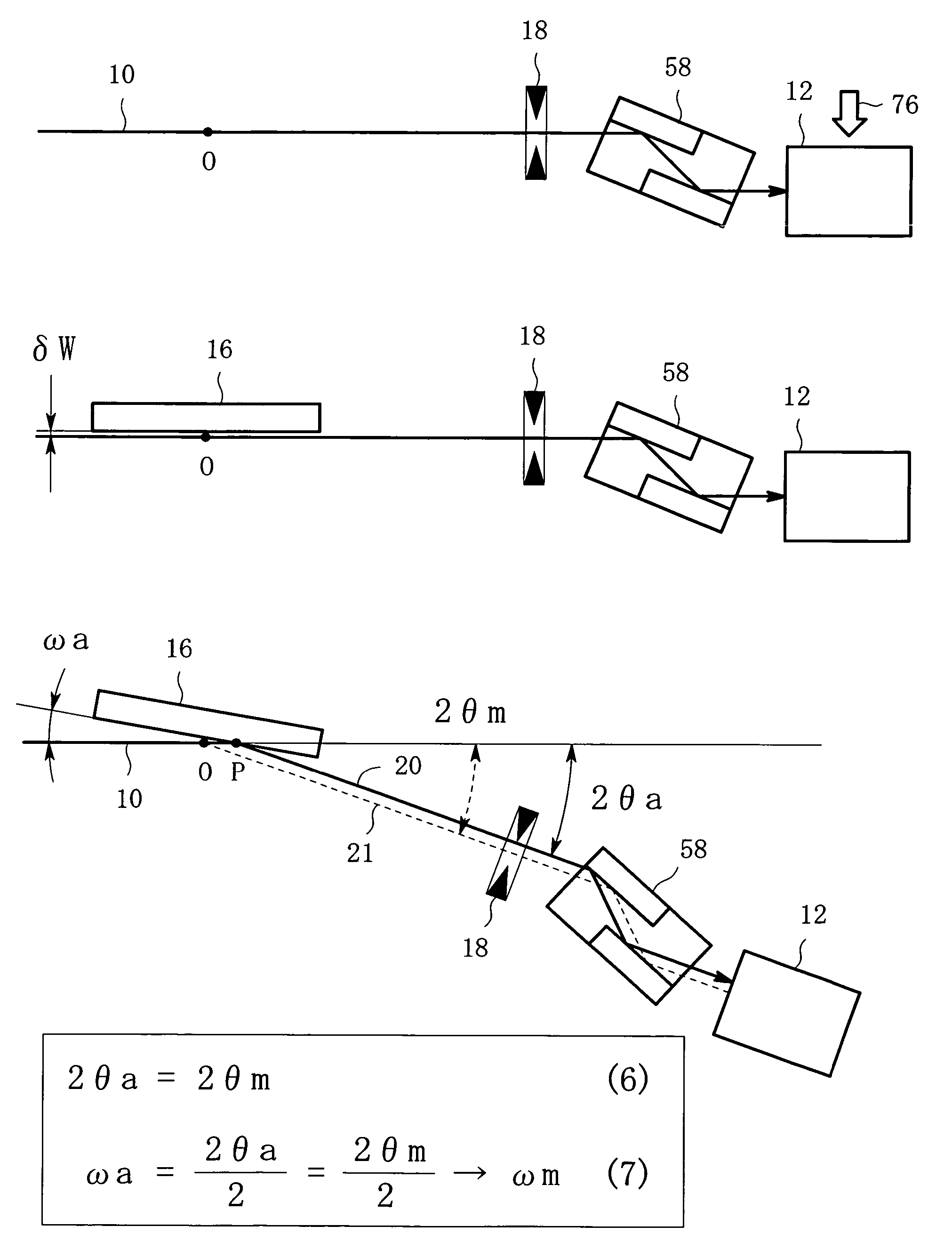
[0014]It is an object of the present invention to provide a method for X-ray reflectance measurement, in which intensities of reflected X-rays are measured for respective incident angles, having improved accuracy and improved repeatability in determining the incident angles.
[0017]The present invention has the advantage that even if the positioning error of the sample exists, the real incident angle is determined with the use of the analyzer crystal so that the measuring scale for the incident angle can be corrected to coincide with the real incident angle. Accordingly, the X-ray reflectance measurement has improved accuracy and improved repeatability in determining the incident angle and can obtain a reflection curve with high accuracy.

Problems solved by technology

Although the X-ray reflectance method has the advantages of the determination of the absolute value of the thickness and the nondestructive measurement, the observed thickness determined by the current X-ray reflectance method is said to be inferior, in view of repeatability, to that obtained by the X-ray photoelectron spectroscopy method or the ellipsometry method.
The inferior repeatability of thickness in the X-ray reflectance method is attributed to inaccurate determination of the incident angle of the incident X-ray which is incident on the surface of the thin film sample.
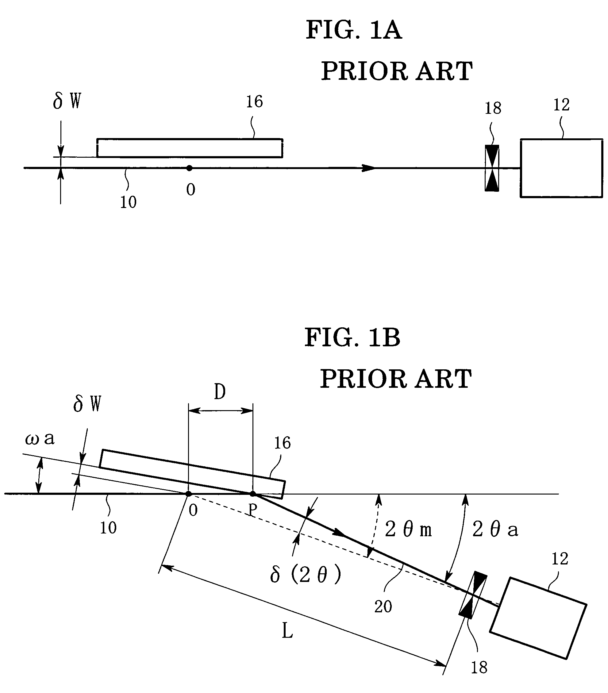
It is very difficult, however, from a practical standpoint to allow the position of the sample surface to coincide with the goniometer center O with accuracy of less than one micrometer.
The existence of such error δW causes deterioration in accuracy of the observed incident angle ω.
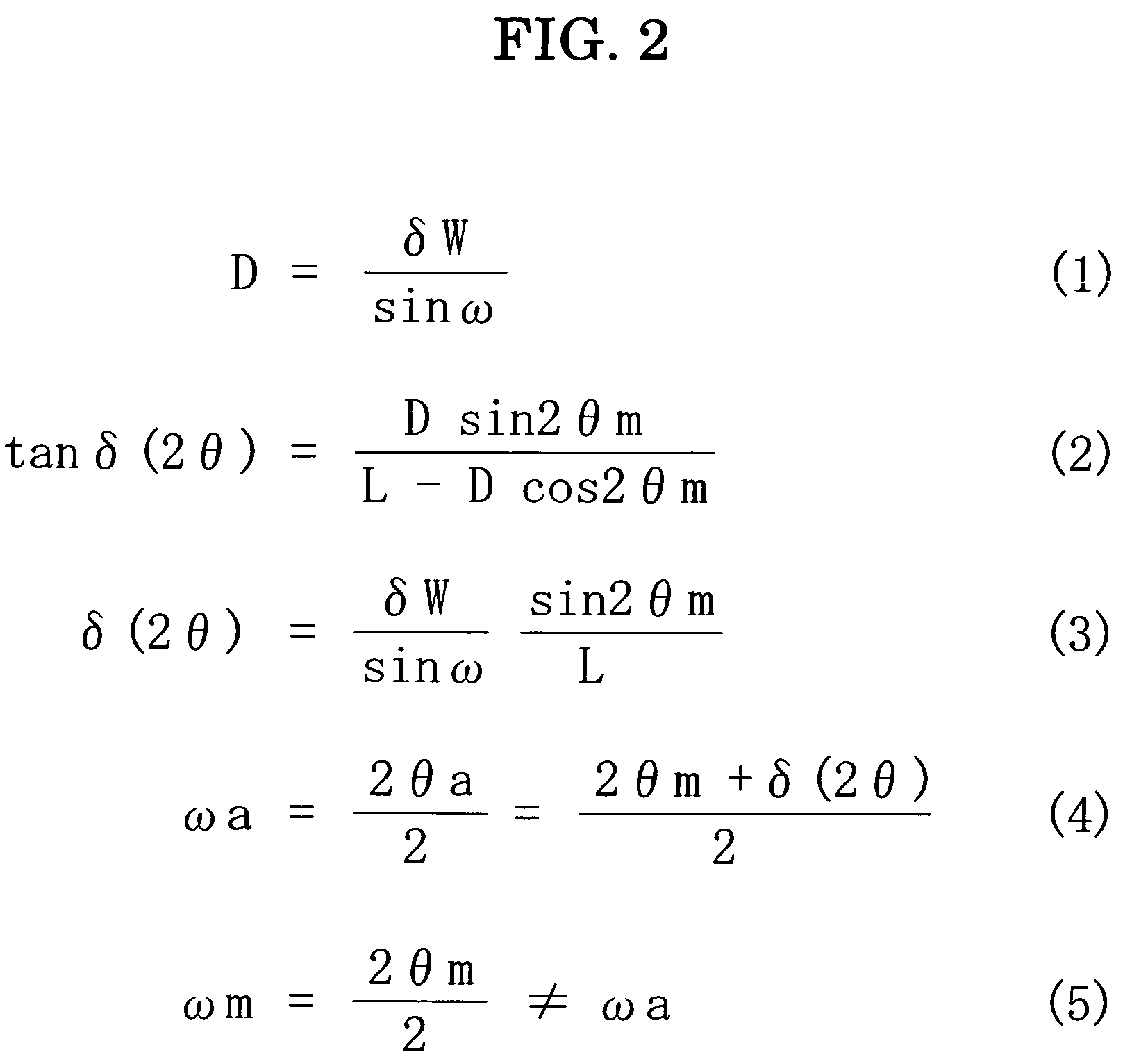
In the conventional method, a reflectance curve is obtained based on the observed incident angle ωm which is different from the real incident angle ωa, and then the thickness of the thin film is determined based on the reflectance curve, resulting in insufficient repeatability of the thickness measurement.
If the position of the sample is adjusted with the usual half-split method, the positional error would be not so large, but it is difficult to position the sample with accuracy of less than one micrometer.
Although the two second is a very small angle, the angular error to such an extent would have a problem in determining the thickness of the thin film with a good repeatability using the X-ray reflectance method.
Especially, it is an important problem in the conventional method that there is no means for verifying how much the difference δ(2θ) is.

Method used


Image

  • Method and apparatus for X-ray reflectance measurement
  • Method and apparatus for X-ray reflectance measurement
  • Method and apparatus for X-ray reflectance measurement

Examples


Embodiment Construction

[0041]An embodiment of the present invention will now be described below with reference to the drawings. FIG. 3 is a perspective view showing one embodiment of an apparatus for X-ray reflectance measurement according to the present invention. The apparatus for X-ray reflectance measurement is comprised of an incident optical system 22, a sample support mechanism 24 and a receiving optical system 26.

[0042]The sample support mechanism 24 has a sample holder 32 whose surface stands upright. The sample support mechanism 24 has an ω-turntable 34 which can turn around an axis of rotation 33 with respect to a base 28. This rotation will be referred to as an ω-rotation. On the other hand, a 2θ-turntable 30 which supports the receiving optical system 26 also can turn around the axis of rotation 33 with respect to the base 28. The rotation of the 2θ-turntable 30 will be referred to as a 2θ-rotation. The 2θ-turntable 30 and the ω-turntable 34 can turn independently of one another. A mechanism ...


PUM

PropertyMeasurementUnit
aaaaaaaaaa
scattering angle 2θmaaaaaaaaaa
angle 2θmaaaaaaaaaa

Abstract

In a method for X-ray reflectance measurement in which an intensity of a reflected X-ray is observed for each incident angle, a measuring scale for the incident angle ω is corrected, before the reflectance measurement, using an analyzer crystal. In the corrective operation, the aperture width of the receiving slit is made wider than in the X-ray reflectance measurement, and the analyzer crystal is inserted in the reflection path, and then the reflected X-ray intensity is detected. In this condition, the incident angle ω of the incident X-ray to the sample surface can be determined accurately, and thus the measuring scale for the incident angle can be corrected. Thereafter, the analyzer crystal is removed from the reflection path, and the X-ray reflectance measurement for the sample surface is carried out.

Description

BACKGROUND OF THE INVENTION[0001]1. Field of the Invention[0002]The present invention relates to a method and an apparatus for measuring a reflectance of specular reflection, i.e., total reflection, of an X-ray which is reflected by a surface of a sample, and especially to a method and an apparatus for X-ray reflectance measurement in which a correct value of an incident angle to the sample surface can be determined accurately to realize high-accurate reflectance measurement.[0003]2. Description of the Related Art[0004]Some methods are known for measuring a thickness of a thin film deposited on a substrate. Of these methods, an X-ray reflectance method is in the spotlight because it can determine the absolute value of the thickness and also it is nondestructive. Although the X-ray reflectance method has the advantages of the determination of the absolute value of the thickness and the nondestructive measurement, the observed thickness determined by the current X-ray reflectance meth...

Claims


Application Information

Patent Timeline
Patent Type & Authority Patents(United States)
IPC IPC(8): G01N23/20
CPCG01B15/02G01N23/201G01N23/207
Inventor OMOTE, KAZUHIKO
Owner RIGAKU CORP
Why Eureka
Try Eureka