
Closed forging method, forging production system using the method, forging die used in the method and system, and preform or yoke produced by the method and system

a technology of closed forging and production system, applied in the direction of mechanical equipment, engine components, metal-working apparatus, etc., can solve the problems of high production cost, high production cost, low yield of products on the basis of forging materials, etc., to enhance the yield of products, improve mechanical features, and improve mechanical features

Active Publication Date: 2007-08-21
SHOWA DENKO KK
View PDF16 Cites 15 Cited by
  • Summary
  • Abstract
  • Description
  • Claims
  • Application Information

AI Technical Summary

Benefits of technology

[0029]In the closed forging method according to the present invention, as described above, there is used a cylindrical forging material that has a volume the same as the volume of a forged product and assumes a shape containing no angular portion and having a ratio of a lateral length of a projection profile of the forging material as viewed in the direction perpendicular to the direction of pressure application to the length of the forging material as measured in the direction of pressure application, which ratio is 1 or less. Since pressure is applied to the side surface of the forging material to cause plastic flow of the forging material to occur along a plurality of branches of a forged product to thereby form layers of metal flow in the branches, the forged product exhibits improved mechanical features and has no flash removal mark. This enhances the yield of products on the basis of the forging material.
[0030]Since plastic flow of the forging material is caused to occur along a plurality of branches of a forged product to thereby form layers of metal flow in the branches, the perform of the upper arm or lower arm that is a suspension part for a vehicle, or the yoke that is a joint part employed in a vehicle suspension, produced through the closed forging method of the present invention exhibits improved mechanical features.
[0031]In the die employed in the closed forging method of the present invention, the shape of a space defined by a combination of a punch, a die and a knock-our or bush, or by a combination of a punch and a die having a drive mechanism has a volume the same as the volume of a forged product and a ratio of a lateral length of a projection profile of the forging material as viewed in the direction perpendicular to the direction of pressure application to the length of the forging material as measured in the direction of pressure application, which ratio is 1 or less. In addition, the die has a configuration that enables pressure to be applied to the side surface of a cylindrical forging material. Therefore, the pressure applied during the forging can be reduced, and the yield of the products on the basis of the forging material can be enhanced.

Problems solved by technology

In such a method, since unwanted flashes are formed around a forged body, the yield of the product on the basis of a forging material is low.
In addition, since the projection area of the forged body as viewed in the direction perpendicular to the direction of pressure application is large, a large, expensive forging machine capable of applying high load is required, resulting in high production cost.
In addition, the method requires steps for machining, resulting in high production cost.
In this method, since unwanted flashes are formed around the preform, the yield of the preform on the basis of the material is low.
In addition, since the projection area of the forged body as viewed in the direction perpendicular to the direction of pressure application is large, a large, expensive forging machine capable of applying high load is required, resulting in high production cost.

Method used


Image

  • Closed forging method, forging production system using the method, forging die used in the method and system, and preform or yoke produced by the method and system
  • Closed forging method, forging production system using the method, forging die used in the method and system, and preform or yoke produced by the method and system
  • Closed forging method, forging production system using the method, forging die used in the method and system, and preform or yoke produced by the method and system

Examples


example 1

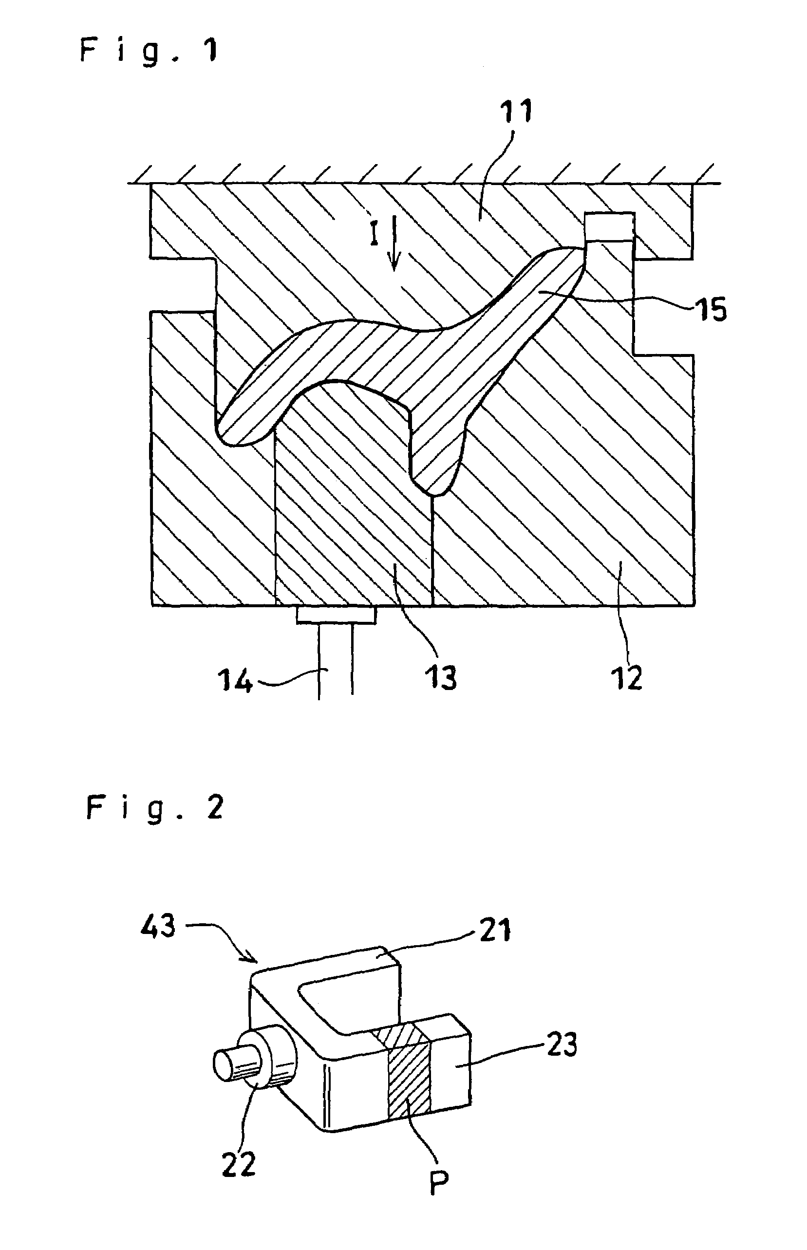
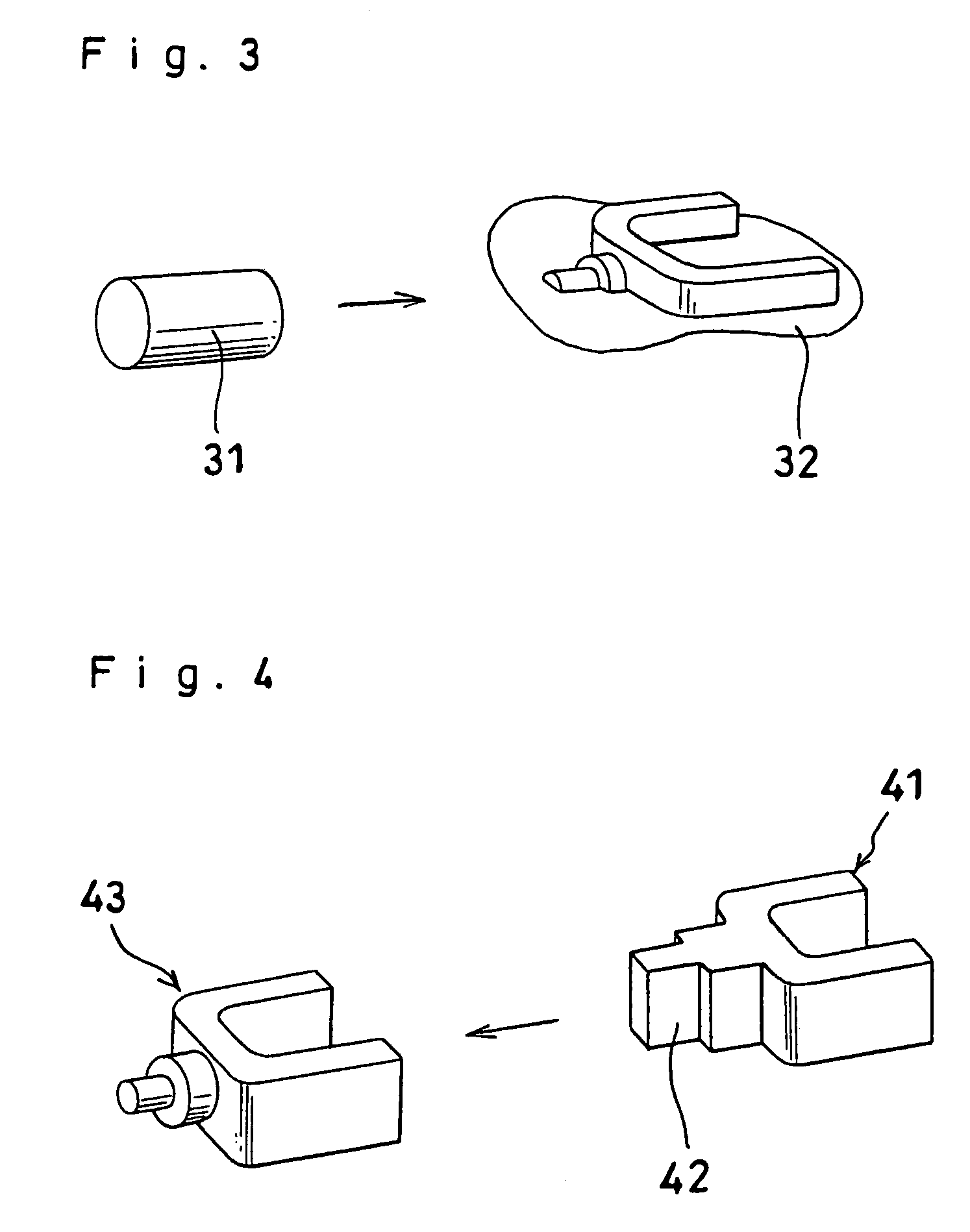
[0117]In order to produce through forging a yoke 43 shown in FIG. 2, which is a joint part employed in a vehicle suspension, a cut piece of JIS 6061 aluminum alloy having the same volume as the yoke 43 was designed as the forging material in the following manner.

[0118]The volume of the yoke 43 was calculated by means of a CAD system programmed in a computer. On the basis of the results of the calculation, the volume of a cut piece was designed to be 38.8 cm3. The volume tolerance of the cut piece was determined to be +1% on the basis of the calculated volume of the yoke.

[0119]Subsequently, the thickness (T) of the cut piece was designed to be 34 mm, which is 0.95 times the lateral length (t) represented by reference letter B (shown in FIG. 14) of a projection profile of a forged product in a direction perpendicular to the pressure application direction represented by reference letter A shown in FIG. 13. On the basis of the volume and thickness of the cut piece, the diameter (R) of t...

example 2

[0135]In order to produce a yoke shown in FIG. 18, which is a joint part employed in a suspension for vehicles, a cut piece of JIS 6061 aluminum alloy having the same volume as the yoke was designed as the forging material in the following manner.

[0136]The volume of the yoke was calculated by means of a CAD system programmed in a computer. On the basis of the results of the calculation, the volume of a cut piece was designed to be 84.0 cm3. The volume tolerance of the cut piece was determined to be ±1% on the basis of the calculated volume of the yoke.

[0137]Subsequently, the thickness of the cut piece was designed to be 30 mm, which is 0.95 times the lateral length (t) represented by reference letter E shown in FIG. 20 of a projection profile of a forged product in the direction perpendicular to the pressure application direction D shown in FIG. 19. On the basis of the volume and thickness of the cut piece, the diameter (R) of the cut piece was determined by use of the equation:

R=2×...

example 3

[0143]The thickness of disk-shaped cut pieces obtained from a round bar material was designed to be 25 mm, which is 0.7 times the lateral length represented by reference letter B shown in FIG. 14. The diameter (R) of the cut pieces was determined to be 44 mm by use of the equation:

R=2×√(38,800 / (25π)).

Here, R satisfies the condition: R≦(longitudinal length (L) represented by reference letter C in FIG. 14).

[0144]By use of the cut pieces, forging was performed in a manner similar to that of Example 1. As a result, since the cut pieces (forging material) were not stabilized in a forging die and were inclined in the die during forging, percent occurrence of forging defects, such as underfill and overlap, in the resultant forged products was 50%.


PUM

PropertyMeasurementUnit
volumeaaaaaaaaaa
thicknessaaaaaaaaaa
diameteraaaaaaaaaa

Abstract

A closed forging method for producing a forged product includes preparing as a forging material a cylindrical cast ingot that has a volume the same as the volume of a forged product and assumes a shape having an upper surface, a lower surface and a side surface and containing no angular portion; and applying pressure to the side surface of the forging material. The shape has a ratio of the lateral length of a projection profile of the forging material as viewed in the direction perpendicular to the direction of pressure application to a length of the forging material as measured in the direction of pressure application is 1 or less. The forged product obtained is a preform of an upper arm or a lower arm with a plurality of branches that is a suspension part for a vehicle or a yoke with a plurality of branches that is a joint part employed in a vehicle suspension. The preform or yoke has metal flow lines along each branch and exhibits enhanced mechanical strength.

Description

CROSS REFERENCE TO RELATED APPLICATIONS[0001]This application is an application filed under 35 U.S.C. § 111(a) claiming the benefit pursuant to 35 U.S.C. § 119(e) (1) of the filing date of U.S. Provisional Application Ser. No. 60 / 281,810 filed. Apr. 6, 2001 pursuant to 35 U.S.C. § 111(b).TECHNICAL FIELD[0002]The present invention relates to a closed forging method, a forging production system using the method, a forging die used in the method and system, and a suspension part for a vehicle and a preform or yoke of the part produced by the method and system.BACKGROUND ART[0003]Joint parts employed in a vehicle suspension include a yoke 43 shown in FIG. 2, which has a plurality of branches 21, 22 and 23.[0004]Conventionally, the yoke has been formed, as shown in FIG. 3, by forging a solid round bar 31 that is a material to be subjected to forging into a forged product having a flash 32 formed at its periphery.[0005]Alternatively, as shown in FIG. 4, a product 43 (i.e., a yoke) has bee...

Claims


Application Information

Patent Timeline
Patent Type & Authority Patents(United States)
IPC IPC(8): B21D31/00B21J5/02B21K1/74B21K1/76B21K3/00
CPCB21J5/02B21K1/74B21K1/76B21K1/762B21K3/00
Inventor NATSUI, MASAYUKINAKAHARA, TAKAFUMI
Owner SHOWA DENKO KK
Features
  • Generate Ideas
  • Intellectual Property
  • Life Sciences
  • Materials
  • Tech Scout
  • Unparalleled Data Quality
  • Higher Quality Content
  • 60% Fewer Hallucinations
Learn More