Driver for Pockels cell and using this Pockels cell within laser systems

Active Publication Date: 2007-08-21
DR THORALD BERGMANN +1
View PDF6 Cites 2 Cited by
  • Summary
  • Abstract
  • Description
  • Claims
  • Application Information

AI Technical Summary

Benefits of technology

[0034]A further application of such laser systems is the generation of specific laser pulse patterns with or without further amplifying these laser pu

Problems solved by technology

Thus it is necessary to increase the voltage of the high voltage source, which also increases the amount of energy consumed per switching action.b) To increase the capcitance ratio by connecting capcaitors in parallel to the high voltage switches will not help, because while increasing the voltage applied to the Pockels cell this measure at the same time will also increase the amount of energy consumed per switching action, this increase in energy being caused by the charging and discharging of the added capacitors.c) The time any switch is closed is usually dictated by its internal wiring.
This will limit the maximum time that voltage can be applied to the Pockels cell.d) This fixed closing time of the high voltage switches will also result in a time difference when both switches open again,

Method used


Image

  • Driver for Pockels cell and using this Pockels cell within laser systems
  • Driver for Pockels cell and using this Pockels cell within laser systems
  • Driver for Pockels cell and using this Pockels cell within laser systems

Examples


Embodiment Construction

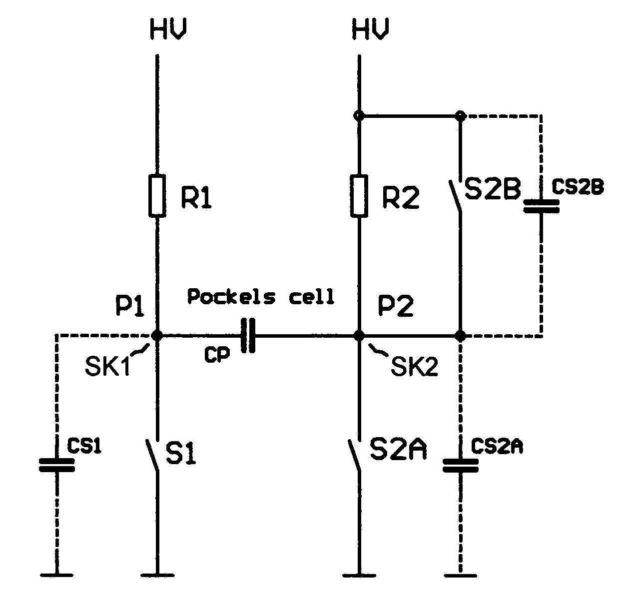
[0042]A first embodiment of the driver according to the invention in FIG. 3a modifies the state-of-the-art H-configuration by adding a high voltage switch S2B in parallel to one of the recharging resistors R2. The intrinsic capacitance of this switch S2b is denoted by CS2B drawn by dashed lines.

[0043]The operation of the driver from FIG. 3a is shown in FIG. 3b. Switch S2B must be closed before closing switch S1. Closing the switch S1 applies the complete voltage from the high voltage power supply to the Pockels cell. Synchronously with closing switch S2A, taking away the voltage across the Pockels cell, switch S2B is opened. During or after the recharging phase switch S2B is closed again.

[0044]FIG. 4 shows another embodiment of the invention where both recharging resistors used in the H-configuration are replaced by switches S1B and S2B. Thus the nodes SK1 and SK2 are connected through only one wire (the first and third wire), containing each one switch (S1B, S2B) with the high volt...


PUM


Abstract

Driver for Pockels cells and using this Pockels cell within laser systems
The driver i.e. the electrical control of the Pockels cell is modified from the standardly known H-configuration using the switches S1, S2A; S1A, S2 A by adding at least one more switch (S2B; S1B; S2B). This switch can either replace the usually used recharging resistors (R2) or can be placed to these in parallel. It is also possible to use an arrangement using 4 switches (S1A, S2A, S1B, S2B) and no recharging resistors at all. Using such a driver with a Pockels cell pulses can be selected in laser systems more efficiently. Pulse sequences with well defined widths and spacing can be produced for certain application.

Description

BACKGROUND OF THE INVENTION[0001]a) Field of the Invention[0002]Driver for Pockels cell and using this Pockels cell in laser systems.[0003]This invention relates to a driver or electrical high voltage control for a Pockels cell and application of a Pockels cell controlled with said driver in a laser system and applications of said laser systems.[0004]A Pockels cell generally consists of a birefringent crystal which is placed into and oriented in an adequate way to a monochromatic and polarized laser beam. In combination with some further optical elements, such as polarizers or mirrors, this Pockels cell can, by applying an electrical voltage ranging from 100V to a few kilovolts[0005]a) allow or disallow the passage of light[0006]b) direct the light on two different paths through an optical system[0007]The voltage necessary to reach the two named states of the system are determined by the crystal parameters and the wavelength of the light used. There are applications of Pockels cells...

Claims


Application Information

Patent Timeline
IPC IPC(8): H01S3/115G02F1/03
CPCG02F1/0327
Inventor BERGMANN, THORALD HORSTKNAPPE, RALF
Owner DR THORALD BERGMANN
Why Eureka
Try Eureka