
Roller guide tape path

a tape path and roller technology, applied in the direction of driving by direct/indirect member action, recording information storage, instruments, etc., can solve the problems of tape speed variation, tape resonance excitation, tape debris generation, etc., and achieve the effect of increasing the length of the tape path

Active Publication Date: 2007-08-28
ORACLE INT CORP
View PDF26 Cites 11 Cited by
  • Summary
  • Abstract
  • Description
  • Claims
  • Application Information

AI Technical Summary

Benefits of technology

"The patent describes a mechanism for guiding tape in a storage device. The mechanism includes multiple guides located far from the cartridge and take-up reels, which prevents interference with the tape path. A non-flanged guide is also included to increase the tape path length and allow the guides to be positioned remotely from the cartridge and take-up reels. The mechanism is designed to optimize the tape path and ensure symmetrical placement of the read / write heads. The technical effect of this mechanism is to improve the performance and reliability of the storage device."

Problems solved by technology

Problems arising from this type of tape guide include friction generated from the tape movement against the fixed flanges which results in tape speed variations, tape resonance excitation, and tape debris generation.
Also, the tape frequently varies in width, so that the flanges must be separated in excess of the tape width which results in vertical tape movement.
Decreasing the thickness of magnetic tape creates difficulties in a tape transport system.
Thinner tape more easily stretches, increasing the possibility of read and write errors.
Thin tape is also susceptible to folding, kinking, creasing, curling and other mechanical damage.
These difficulties are exacerbated by complex tape transport systems requiring rollers, guides, and the like to drive the tape and position the tape relative to the tape head.

Method used


Image

  • Roller guide tape path
  • Roller guide tape path
  • Roller guide tape path

Examples


Embodiment Construction

[0017]A preferred embodiment of the present invention and its advantages are better understood by referring to the figures, like numerals being used for like and corresponding parts of the accompanying figures.

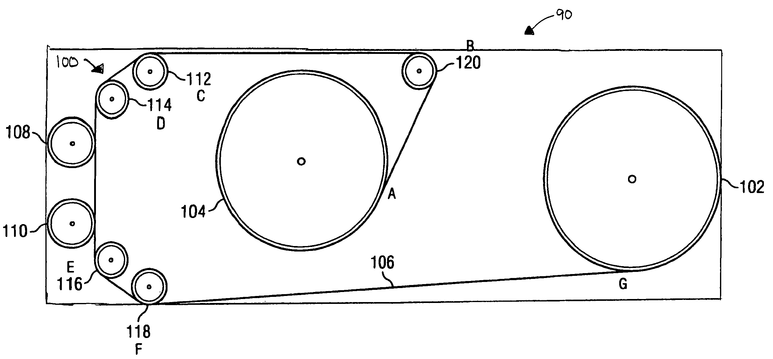
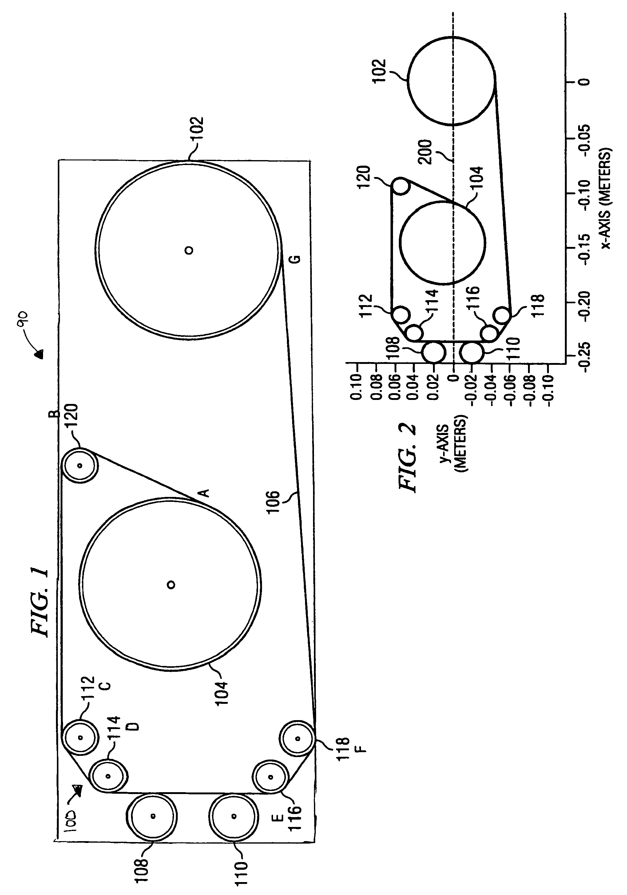
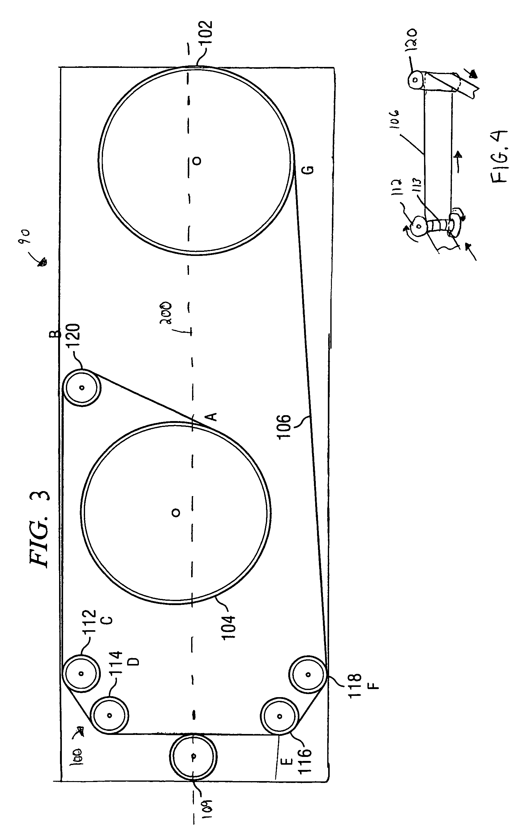
[0018]FIG. 1 is a top view of a tape guide mechanism 100 in a storage device 90 including an optimized roller guide tape path in accordance with the present invention. FIG. 2 is a top view of tape guide mechanism 100 of FIG. 1 depicting preferred dimensions of the various components of the mechanism using a two-axis coordinate system in accordance with the present invention. The dimensions of the x-axis and y-axis depicted by FIG. 2 are in meters.

[0019]Referring to FIGS. 1 and 2, the tape guide mechanism 100 includes a cartridge reel 102 for supplying tape to a drive reel 104. The tape 106 travels in a tape path between reels 102 and 104. The entire tape path extends from point A to point G.

[0020]The present invention describes a tape guide mechanism that defines a long tape p...


PUM


Abstract

A tape guide mechanism in a storage device is disclosed for defining an improved roller guide tape path. A cartridge reel is provided for supplying tape to a take-up reel. Multiple flanged guides are provided located remotely from the cartridge and take-up reels. A non-flanged post guide is provided located proximate to the take-up reel for increasing a length of the tape path and for permitting the flanged guides to be located remotely from the cartridge and take-up reels so that the flanged guides are not located in proximity to the cartridge or take-up reels. An axis of symmetry exists longitudinally about one or two read / write heads. The tape path length is generally symmetrically disposed about this axis of symmetry.

Description

BACKGROUND OF THE INVENTION[0001]1. Field of the Invention[0002]The present invention relates generally to data storage devices and particularly to an improved roller guide tape path within a data storage device.[0003]2. Background of the Invention[0004]Magnetic tape is frequently used to store digital data. Such tape may be housed in a tape cartridge that protects the tape from damage. Tape drive systems for reading information from or writing information on magnetic tapes require tape guides to ensure that the tape is positioned correctly relative to the magnetic read / write heads in order to minimize lateral tape motion (LTM).[0005]One type of prior tape path uses rollers having integral non-compliant fixed upper and lower flanges to guide the tape. Problems arising from this type of tape guide include friction generated from the tape movement against the fixed flanges which results in tape speed variations, tape resonance excitation, and tape debris generation. Also, the tape fre...

Claims


Application Information

Patent Timeline
Patent Type & Authority Patents(United States)
IPC IPC(8): G03B23/02
CPCG11B15/28G11B15/29
Inventor UNDERKOFLER, DANIELVANDERHEYDEN, WILLIAM J.
Owner ORACLE INT CORP
Learn More