High voltage device with a particle trap

a high-voltage switch and particle trap technology, applied in the field of high-voltage switch technology, can solve the problems of high dielectric load on isolator parts in high-voltage switching devices, poor dielectric strength and hence operational reliability, etc., and achieve the effect of high operational reliability

Active Publication Date: 2007-08-28
HITACHI ENERGY LTD
View PDF6 Cites 20 Cited by
  • Summary
  • Abstract
  • Description
  • Claims
  • Application Information

AI Technical Summary

Benefits of technology

[0007]One object of the invention is therefore to provide a high-voltage switching device of the type mentioned initially which does not have the disadvantages mentioned above. One particular aim is to provide a high-voltage switching device which has high operational reliability.

Problems solved by technology

A high-voltage switching device such as this has the disadvantage that its dielectric strength and hence its operational reliability are not ensured well during operation.
Isolator parts in high-voltage switching devices are subject to high dielectric loads and are thus particularly sensitive to faults.
An isolator part having a surface which is aligned essentially horizontally and faces the interior of the switching device is particularly susceptible to foreign body particles which are arranged on the surface.
In particular, however, foreign body particles can also arise during operation of the high-voltage switching device.
The wear which occurs as a result of movement of the moving contact piece means that foreign body particles can be produced.
In particular, a particularly large number of foreign body particles are thus produced in switching gaps as a result of the friction between the contact pieces.
If the field strength is sufficiently high, foreign body particles can be moved by the forces which are produced by the electrical field and act on the foreign body particles, thus leading to flashovers, particularly at points which are subject to particularly high dielectric loads.

Method used


Image

  • High voltage device with a particle trap
  • High voltage device with a particle trap
  • High voltage device with a particle trap

Examples


Embodiment Construction

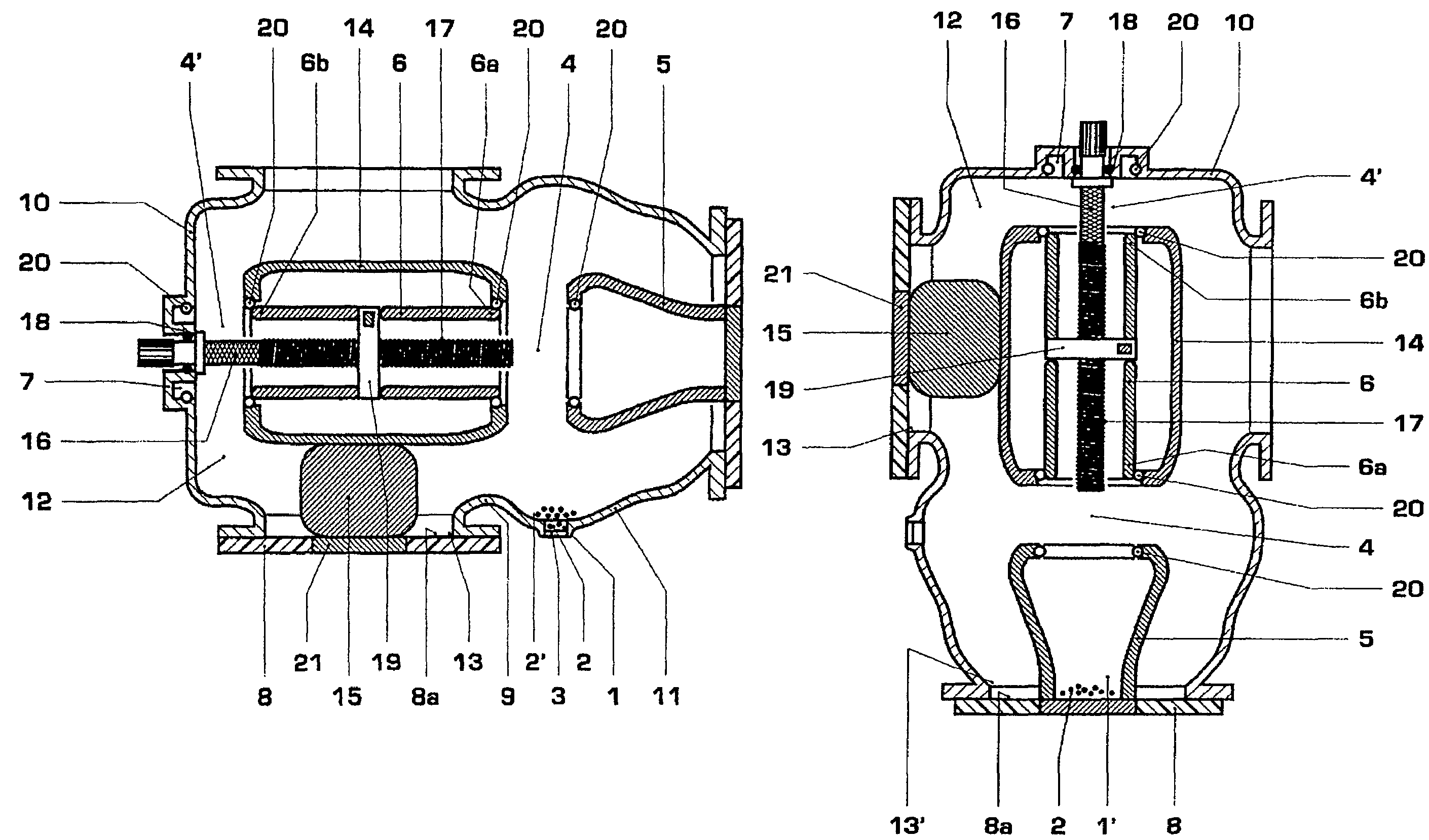
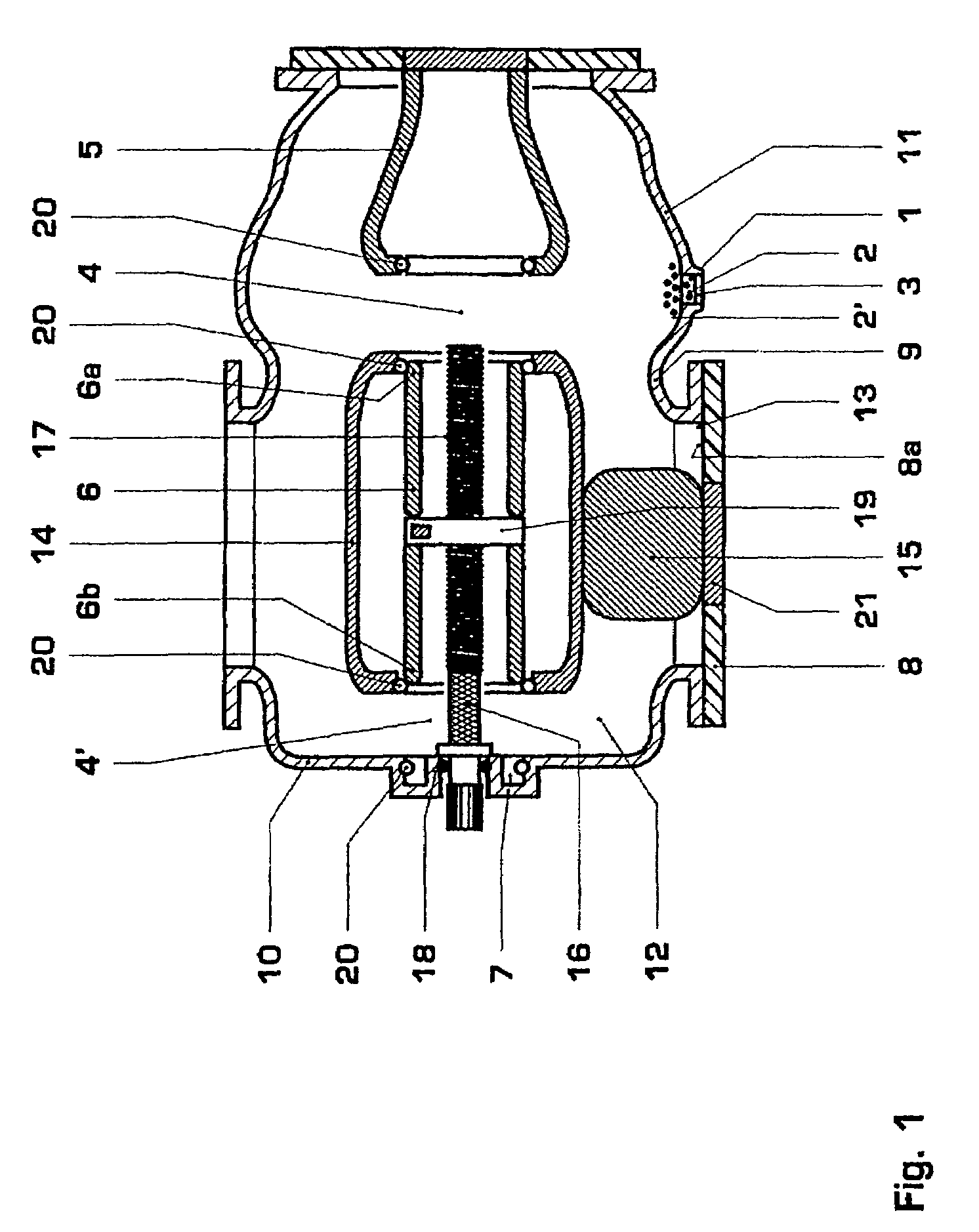
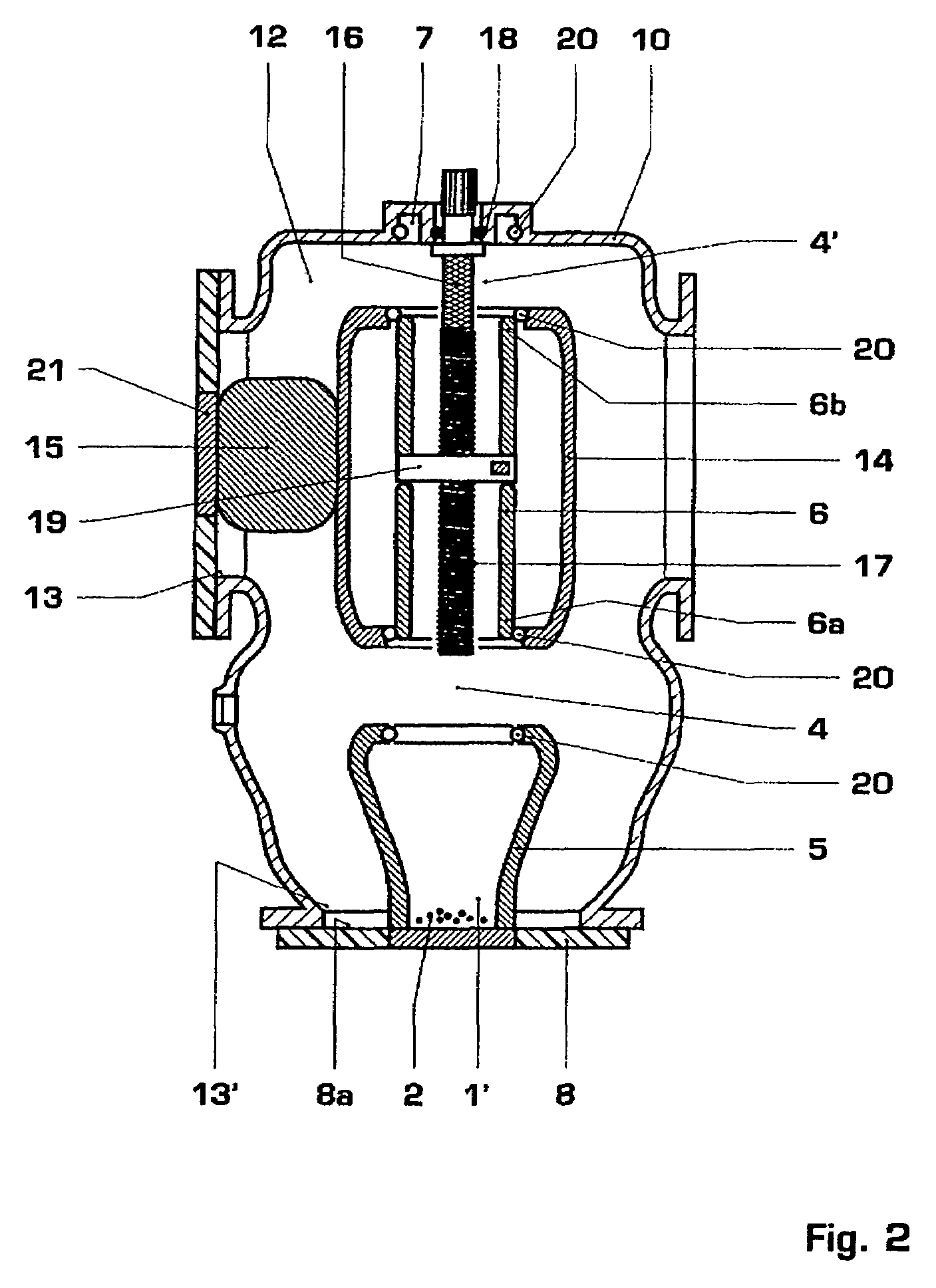
[0041]FIG. 1 shows a grounding device / disconnector according to the invention in a first installation position. This grounding device / disconnector can also be used in at least two other installation positions, which are illustrated in FIGS. 2 and 3.

[0042]The grounding device / disconnector has metal encapsulation 10 which is filled with an insulating gas 12, preferably SF6. Alternatively, there could also be a vacuum within the encapsulation 10. Furthermore, the encapsulation 10 contains active parts, which are supported on an isolator part 8. A connecting piece 15 which is supported on a metal part 21 (internal fitting in the isolator part 8) which is provided in the isolator part 8 produces an electrical connection between the active part and the exterior. The connecting piece 15 supports a contact tube mount 14 to which a contact tube 6 is fitted which makes contact with the contact tube mount 14 by means of a spiral spring contact 20. The contact tube can be moved between three po...


PUM


Abstract

The high-voltage switching device used in one installation position and has metallic encapsulation (10) a switching gap (4) and a particle trap (1) for holding foreign body particles (2), and is characterized in that in the one installation position, the particle trap (1) is arranged vertically underneath the switching gap (4), in the one installation position, an isolator part (8) is provided, which has a surface (8a) aligned essentially horizontally and faces the interior of the high-voltage switching device, with a metallic wall (9), which is higher than the particle trap (1; 1′), being arranged between the isolator part (8) and the particle trap (1; 1′). The particle trap (1) has a viewing window (3). If the high-voltage switching device is a disconnector, this viewing window (3) may be identical to the viewing window (3) for visual access to the visible disconnecting gap (4) of the disconnector. The high-voltage switching device is used particularly advantageously in a second installation position and has a second particle trap, with the second particle trap arranged vertically underneath the switching gap (4) in the second installation position. This results in the high-voltage switching device having good operational reliability and a low susceptibility to defects.

Description

RELATED APPLICATION [0001]The present application claims priority under 35 U.S.C. 119 to European Application No. 04405115.9 filed Feb. 27, 2004, the contents of which are hereby incorporated by reference in their entirety.BACKGROUND[0002]1. Technical Field[0003]The invention relates to the field of high-voltage switch technology. It relates to a high-voltage switching device and to a method for separation of foreign body particles in a high-voltage switching device as claimed in the precharacterizing clause of the independent claims, and to a high-voltage installation as claimed in claim 10.[0004]2. Prior Art[0005]A high-voltage switching device such as this is known, for example, from DE 41 20 309, which describes a particle trap which is in the form of a connecting stub that is closed by a cover and whose inside is provided with a protective coating. A particle trap such as this is intended for use in high-voltage switching devices which have grounded, metallic encapsulation encl...

Claims


Application Information

Patent Timeline
Patent Type & Authority Patents(United States)
IPC IPC(8): H02G1/00H02B13/055H01H33/24H01H33/56H02B13/02H02B13/045H02B13/065H02G5/00H02G5/06
CPCH01H33/245H01H33/56H01H2009/0292H02B1/04
Inventor HOLAUS, WALTERPAVLOVIC, BOJANGARCIA, MIGUELBLEIKER, DANIELSOLOGUREN-SANCHEZ, DIEGO
Owner HITACHI ENERGY LTD
Why Eureka
Try Eureka